Mitsubishi Colt Ralliart. Manual - part 141
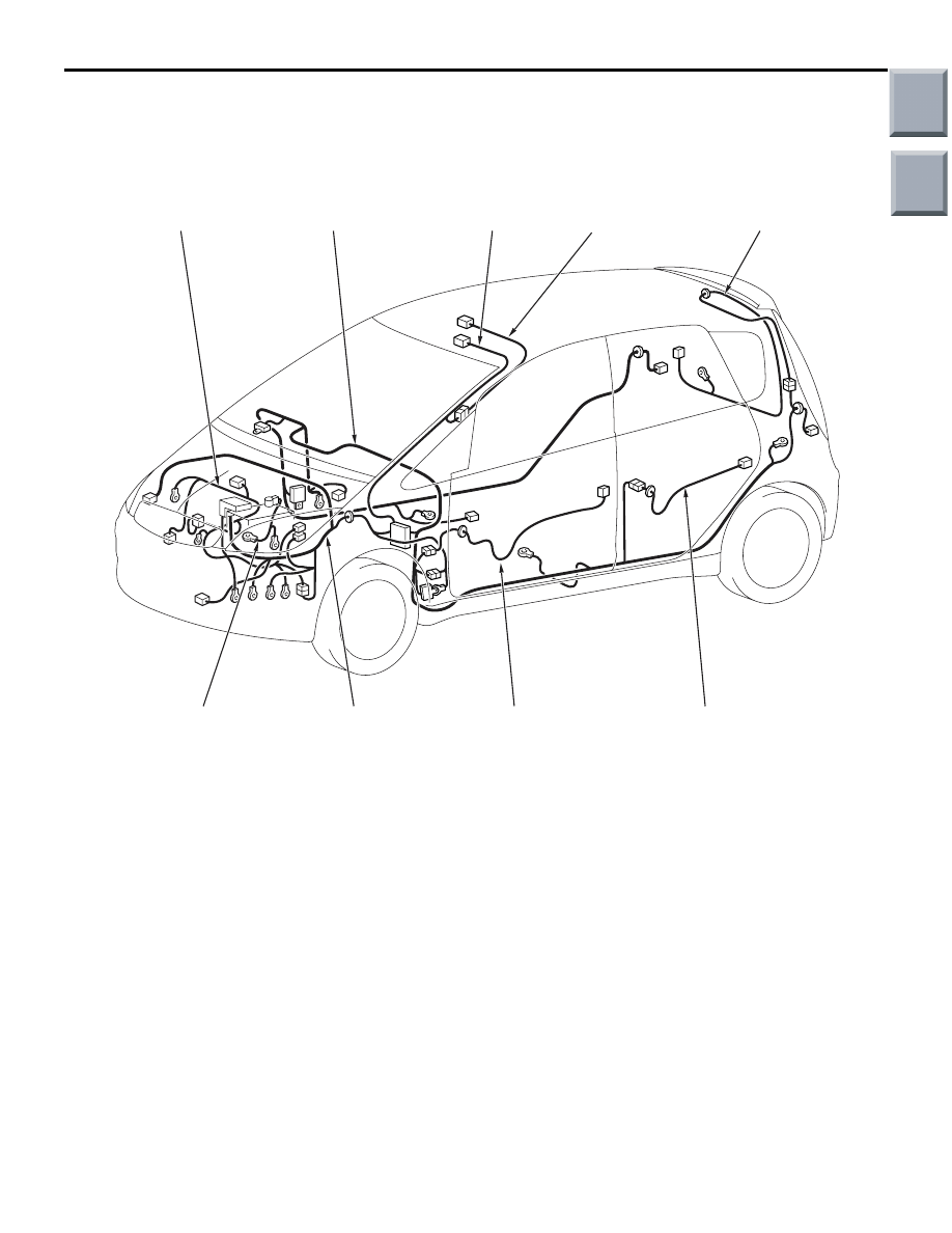
OVERALL CONFIGURATION DIAGRAM
CONFIGURATION DIAGRAMS
80-2
OVERALL CONFIGURATION DIAGRAM
M1801000101603
AC405145
AC600827AC
Control wiring
harness
Battery wiring
harness
Front wiring
harness
Front door
wiring harness
Rear door
wiring harness
Instrument panel
wiring harness
Pillar wiring
harness
Roof wiring
harness
Tailgate wiring
harness
*
*
NOTE:
.
1. This illustration shows only major wiring harnesses.
2. *: also equipped at the right side.
Main
Index
Group
TOC