Mitsubishi Colt Ralliart. Manual - part 92
 

  Index      Mitsubishi     Mitsubishi Colt Ralliart - service repair manual


Search            


Content   ..  90  91  92  93   ..


Mitsubishi Colt Ralliart. Manual - part 92


TROUBLESHOOTING

MULTIPORT FUEL INJECTION (MPI) <4A9>

13A-322

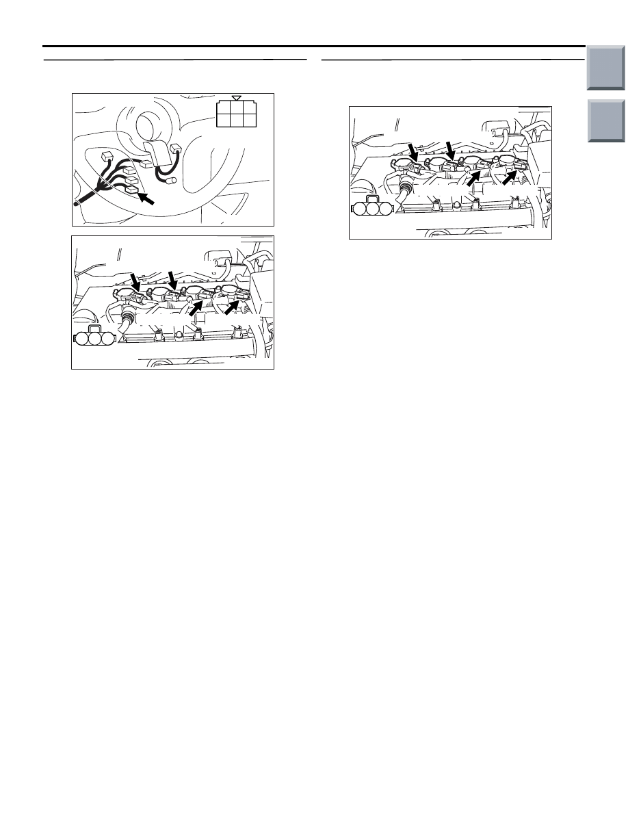
STEP 4. Connector check: B-141 ignition switch 
connector

Q: Is the check result normal? 

YES : 

Check intermediate connectors A-17, B-112 

and B-129, and repair if necessary. If 
intermediate connectors are normal, check 
and repair harness between ignition switch 
connector and ignition coil connector.

a. Check and repair harness between 

B-141 (terminal No. 2) ignition switch 
connector and A-135 (terminal No. 1) 
No. 1 ignition coil connector.

b. Check and repair harness between 

B-141 (terminal No. 2) ignition switch 
connector and A-127 (terminal No. 1) 
No. 2 ignition coil connector.

c. Check and repair harness between 

B-141 (terminal No. 2) ignition switch 
connector and A-126 (terminal No. 1) 
No. 3 ignition coil connector.

d. Check and repair harness between 

B-141 (terminal No. 2) ignition switch 
connector and A-123 (terminal No. 1) 
No. 4 ignition coil connector.

• Check power supply line for 

open/short circuit.

NO : 

Repair or replace the connector.

STEP 5. Perform resistance measurement at 
A-123, A-126, A-127 and A-135 ignition coil 
connectors.

• Disconnect connector, and measure at harness 

side.

• Resistance between terminal No. 2 and earth.

OK: Continuity (2 

 or less)

Q: Is the check result normal? 

YES : 

Go to Step 6 .

NO : 

Check and repair harness between ignition 

coil connector and body earth

a. Check and repair harness between 

A-135 (terminal No. 2) No. 1 ignition 
coil connector and body earth.

b. Check and repair harness between 

A-127 (terminal No. 2) No. 2 ignition 
coil connector and body earth.

c. Check and repair harness between 

A-126 (terminal No. 2) No. 3 ignition 
coil connector and body earth.

d. Check and repair harness between 

A-123 (terminal No. 2) No. 4 ignition 
coil connector and body earth.

• Check earthing line for open 

circuit and damage.

AK402054

B-141

AC

Connector: B-141

1

2

3

4

5

6

B-141 Harness
side connector

AK402013

1

2

3

A-135 (DG) A-127 (DG)

A-126 (DG)

A-123 (DG)

Connector: A-123, A-126, A-127, A-135

AC

Harness side
connector

AK402013

1

2

3

A-135 (DG) A-127 (DG)

A-126 (DG)

A-123 (DG)

Connector: A-123, A-126, A-127, A-135

AC

Harness side
connector

Main

Index

Group

TOC

TROUBLESHOOTING

MULTIPORT FUEL INJECTION (MPI) <4A9>

13A-323

STEP 6. Check harness between ignition coil 
connector and engine-ECU connector or 
engine-CVT-ECU connector.

a. Check and repair harness between A-135 (termi-

nal No. 3) No. 1 ignition coil connector and A-114 
(terminal No. 10) engine-ECU connector or 
engine-CVT-ECU connector.

b. Check and repair harness between A-127 (termi-

nal No. 3) No. 2 ignition coil connector and A-114 
(terminal No. 25) engine-ECU connector or 
engine-CVT-ECU connector.

c. Check and repair harness between A-126 (termi-

nal No. 3) No. 3 ignition coil connector and A-114 
(terminal No. 40) engine-ECU connector or 
engine-CVT-ECU connector.

d. Check and repair harness between A-123 (termi-

nal No. 3) No. 4 ignition coil connector and A-114 
(terminal No. 55) engine-ECU connector or 
engine-CVT-ECU connector.

• Check signal line for short circuit and dam-

age.

Q: Are the check results normal? 

YES : 

Go to Step 7 .

NO : 

Repair the damaged harness wire.

STEP 7. Check harness between ignition switch 
connector and ignition coil connector.

NOTE: Before checking harness, check intermediate 
connectors A-17, B-112 and B-129, and repair if nec-
essary.

a. Check and repair harness between B-141 (termi-

nal No. 2) ignition switch connector and A-135 
(terminal No. 1) No. 1 ignition coil connector.

b. Check and repair harness between B-141 (termi-

nal No. 2) ignition switch connector and A-127 
(terminal No. 1) No. 2 ignition coil connector.

c. Check and repair harness between B-141 (termi-

nal No. 2) ignition switch connector and A-126 
(terminal No. 1) No. 3 ignition coil connector.

d. Check and repair harness between B-141 (termi-

nal No. 2) ignition switch connector and A-123 
(terminal No. 1) No. 4 ignition coil connector.

• Check power supply line for damage.

Q: Are the check results normal? 

YES : 

Go to Step 8 .

NO : 

Repair the damaged harness wire.

STEP 8. Check ignition coil spark.

Q: Is the check result normal? 

YES : 

Replace spark plug.

NO : 

Go to Step 9 .

AK402013

1

2

3

A-135 (DG) A-127 (DG)

A-126 (DG)

A-123 (DG)

Connector: A-123, A-126, A-127, A-135

AC

Harness side
connector

AK402745

6

4

2

5

3

1

9

7

8

10

11

12

13

14

15

16

17

18

19

20

21

22

23

24

25

26

27

28

29

30

31

32

33

34

35

36

37

38

39

40

41

42

43

44

45

46

47

48

49

50

51

52

53

54

55

56

57

58

59

60

61

62

63

64

65

66

L

AD

A-114

Connector: 

A-114

Harness side connector

Engine-ECU <M/T> or
engine-CVT-ECU <CVT>

Battery

AK402054

B-141

AC

Connector: B-141

1

2

3

4

5

6

B-141 Harness
side connector

AK402013

1

2

3

A-135 (DG) A-127 (DG)

A-126 (DG)

A-123 (DG)

Connector: A-123, A-126, A-127, A-135

AC

Harness side
connector

Main

Index

Group

TOC

TROUBLESHOOTING

MULTIPORT FUEL INJECTION (MPI) <4A9>

13A-324

STEP 9. Replace ignition coil.

• After replacing the ignition coil, re-check the trou-

ble symptoms.

Q: Dose trouble symptom persist? 

YES : 

Intermittent malfunction (Refer to GROUP 

00 

− How to Use 

Troubleshooting/Inspection Service Points 

− 

How to Cope with Intermittent Malfunctions 

P.00-13

).

NO : 

Replace engine-ECU <M/T> or 
engine-CVT-ECU <CVT>.

Main

Index

Group

TOC

TROUBLESHOOTING

MULTIPORT FUEL INJECTION (MPI) <4A9>

13A-325

Inspection Procedure 29: Purge control solenoid valve system

OPERATION

• Power is supplied to the purge control solenoid 

valve (terminal No. 2) from the engine control 
relay (terminal No. 4).

• The engine-ECU <M/T> or engine-CVT-ECU 

<CVT> (terminal No. 38) makes the power tran-
sistor in the unit be in ON position, and that 
makes currents go on the purge control solenoid 
valve (terminal No. 1).

AK402707

3

1

2

4

1 2

19

21

20

18

17

16

15

14

1213

11

8 9

L

10

37
52 53 54 555657585960616263646566

38 39 404142434445464748495051

22 23 24 252627282930313233343536

7

5

3

1

6

4

2

Engine
control
relay

B-106

4

2

38

Engine-ECU <M/T> or
engine-CVT-ECU <CVT>

To engine-ECU <M/T> or
engine-CVT-ECU <CVT>

    A-108
MU802779

B-112

A-17

B-108

Purge control
solenoid valve

1

2

4

6

Purge Control Solenoid Valve Circuit

R

R

L-R

3

1

A-114

1

1

R

Fusible link

16

20A

J/B

AC

Wire colour code
B: Black  LG: Light green  G: Green  L: Blue  W: White  Y: Yellow  SB: Sky blue  BR: Brown  O: Orange  GR: Gray
R: Red  P: Pink  V: Violet  Pu: Purple

Main

Index

Group

TOC


Content   ..  90  91  92  93   ..