Mitsubishi Colt Ralliart. Manual - part 87
TROUBLESHOOTING
MULTIPORT FUEL INJECTION (MPI) <4A9>
13A-302
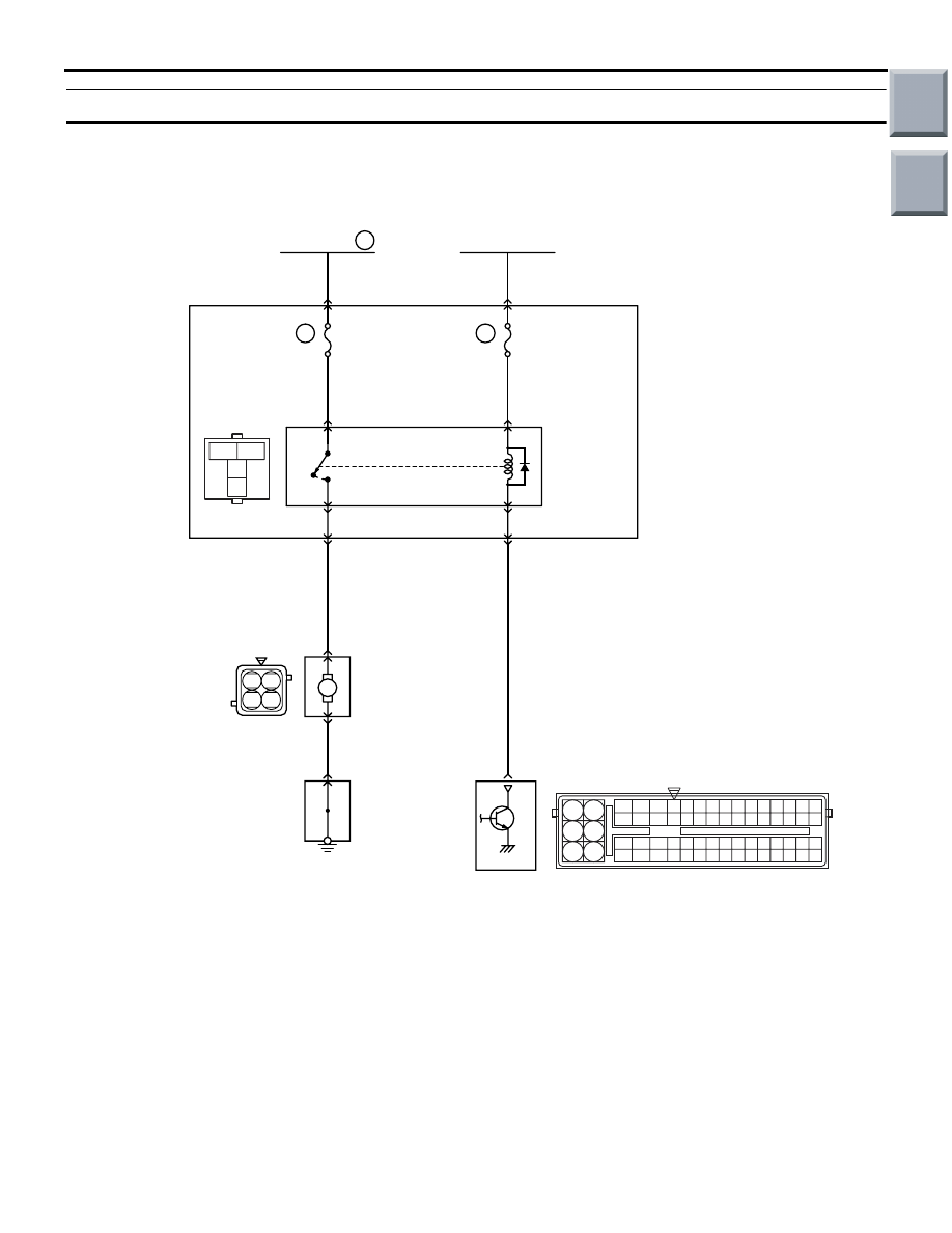
Inspection Procedure 25: Fan control relay system
OPERATION
• The battery voltage is applied to the cooling fan
control relay coil (terminal No. 1) from the ignition
switch.
• The engine-ECU <M/T> or engine-CVT-ECU
<CVT> (terminal No. 95) turns on the switch of
the power transistor on the unit, and then turns
on the switch of the relay by applying the electri-
cal current to the cooling fan control relay coil.
• When the cooling fan control relay is in ON posi-
tion, the battery voltage is applied to the cooling
fan motor (terminal No. 1) from the cooling fan
control relay (terminal No. 4).
FUNCTION
• When the cooling fan control relay is in ON posi-
tion, the fan motor rotates.
AK402704
M
3
1
2
4
1 2
3 4
R
92 93 94 95969798
77 78 79 808182838485868788899091
99
100
107 108 109 110 111112113114115116117118119120121
122 123 124 125126127128129130131132133134135136
101102103104105106
71 72
73 74
75 76
6
Cooling
fan
motor
J/C
Cooling fan
control
relay
Engine-ECU <M/T> or
engine-CVT-ECU <CVT>
B-109
R-L
B-110
B-108
3
1
1
R
Fusible link
3
40A
L
B
J/B
14
95
B-130
1
3
L-R
Ignition switch (IG2)
41
7.5A
1
2
2
A-08
B-114
A-20
MU802223
A-31
AD
Cooling Fan Control Relay Circuit
4
2
Wire colour code
B: Black LG: Light green G: Green L: Blue W: White Y: Yellow SB: Sky blue BR: Brown O: Orange GR: Gray
R: Red P: Pink V: Violet Pu: Purple
Main
Index
Group
TOC