Mitsubishi Colt Ralliart. Manual - part 5
CAMSHAFT
ENGINE MECHANICAL <4A9>
11A-17
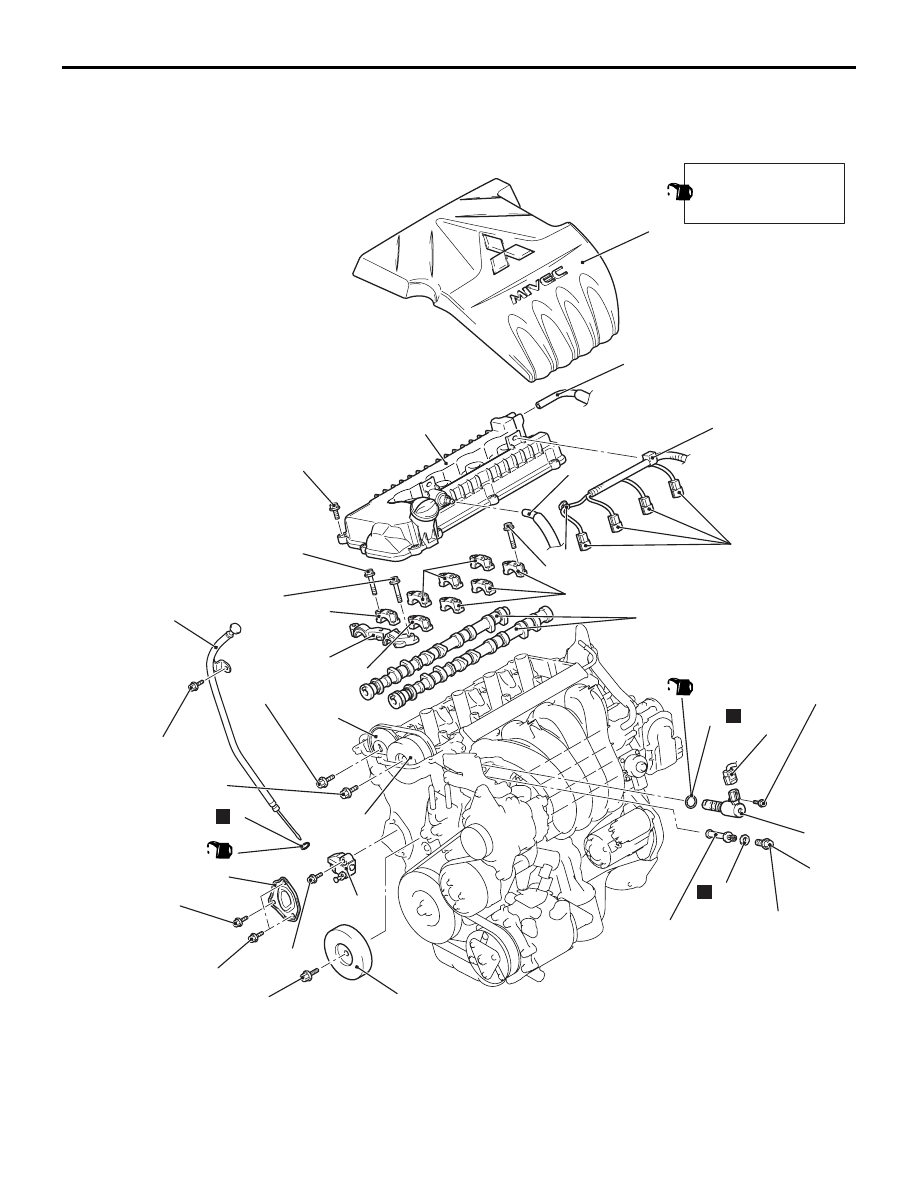
CAMSHAFT
REMOVAL AND INSTALLATION
M1112007800111
AC507705
2
16
12
11
10
8
6
14
5
4
3
AB
N
7.6 ± 0.6 N·m
9.0 ± 1.0 N·m
8.4 ± 0.6 N·m
88 ± 10 N·m
8.4 ± 0.6 N·m
5
8.4 ± 0.6 N·m
13
65 ± 5 N·m
20 ± 1 N·m
15
15
15
11 ± 1 N·m
11 ± 1 N·m
17
19
18
7.6 ± 0.6 N·m
N
22
21
44 ± 5 N·m
20
15
7
N
1
9
49 ± 9 N·m
Apply engine oil to all
moving parts before
installation.
(Engine oil)
(Engine oil)
Camshaft removal steps
•
Air cleaner assembly removal
(Refer to GROUP 15, Air Cleaner
).
1.
Engine cover
•
Ignition coil (Refer to GROUP 16,
Ignition System
− Ignition Coil
<<
A
>>
•
Cowl top panel (Refer to GROUP
42, Loose Panel
).
Camshaft removal steps