Mitsubishi 380. Manual - part 975


  Index      Mitsubishi     Mitsubishi 380 - service repair manual 2005 year


Search            


Content   ..  973  974  975  976   ..


Mitsubishi 380. Manual - part 975


INPUT SHAFT

MANUAL TRANSMISSION OVERHAUL

22B-13

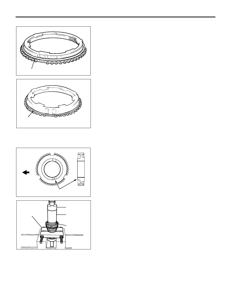
>>D<< SYNCHRONIZER SPRING INSTALLATION

AK201638AD

Synchronizer spring

AKX00951

Synchronizer

spring

AE

Install the synchronizer spring to the illustrated position of the 
synchronizer ring and outer synchronizer ring.

.

>>E<< 3RD-4TH SPEED SYNCHRONIZER HUB 
INSTALLATION

AK302753AB

Installation

direction

Groove

AK201639

MD998813

MD998812

MD998825

MD998801

AD

1. Using special tool Bearing remover (MD998801), support 

the 2nd speed gear portion of the input shaft, and then set 
them on the press.

2. Make sure that the inner synchronizer ring has been 

perfectly matched to the 3rd speed gear cone.

3. Check the installation direction of the 3rd-4th speed 

synchronizer hub, and put it on the input shaft.

4. Using special tools, press install the 3rd-4th speed 

synchronizer hub with the press.

• Installer cap (MD998812)

• Installer-100 (MD998813)

• Installer adapter (MD998825)

5. Make sure that the outer synchronizer ring can rotate freely.

.

INPUT SHAFT

MANUAL TRANSMISSION OVERHAUL

22B-14

>>F<< SYNCHRONIZER SLEEVE INSTALLATION

AK400081AC

Identification

groove

Installation

direction

(3rd speed side)

1. Check the installation direction of the synchronizer sleeve, 

and install it onto the 3rd-4th speed synchronizer hub.

AKX00928AD

Teeth with

raised tips

Deep grooves 

between the teeth

2. Install the synchronizer sleeve so that the areas with teeth 

that have raised tips (three areas total) are aligned with the 
areas on the synchronizer hub that have deep grooves 
between the teeth (three areas total).

.

>>G<< 4TH SPEED GEAR SLEEVE INSTALLATION

AK201640

MD998812

MD998813

MD998825

MD998801

AD

1. Using special tool Bearing remover (MD998801), support 

the 2nd speed gear portion of the input shaft, and then set 
them on the press.

2. Using special tools, press install the 4th speed gear sleeve 

with the press.

• Installer cap (MD998812)

• Installer-100 (MD998813)

• Installer adapter (MD998825)

.

>>H<< 5TH SPEED GEAR INSTALLATION

AK201641

MD998812

MD998813

MD998825

MD998801

AD

1. Using special tool Bearing remover (MD998801), support 

the 2nd speed gear portion of the input shaft, and then set 
them on the press.

2. Using special tools, press install the 5th speed gear in the 

input shaft.

• Installer cap (MD998812)

• Installer-100 (MD998813)

• Installer adapter (MD998825)

.

INPUT SHAFT

MANUAL TRANSMISSION OVERHAUL

22B-15

>>I<< THRUST PLATE INSTALLATION

AK201642AD

Thrust

plate

Surface

stamped wit

identificat

mark

1. Install the thickest thrust plates that can be fitted in the 

groove of input shaft. Install the thrust plate so the surface 
stamped with the identification mark is facing up.

2. Make sure that the 5th speed gear end play meets the 

standard value.

Standard value: 0 

 0.09 mm

.

>>J<< THRUST PLATE STOPPER INSTALLATION

AK201643

MD998812

MD998813

MD998825

AD

Install the thrust plate stopper by pressing special tools by 
hand. Make sure that it is not tilted.

• Installer cap (MD998812)

• Installer-100 (MD998813)

• Installer adapter (MD998825)

.

>>K<< BALL BEARING INSTALLATION

AK201644

MD998812

MD998819

MD998801

AD

1. Using special tool Bearing remover (MD998801), support 

the 2nd speed gear portion of the input shaft, and then set 
them on the press.

2. Using special tools, press install the ball bearing in the input 

shaft.

• Installer cap (MD998812)

• Installer adapter (MD998819)

.

>>L<< SNAP RING INSTALLATION

AK201645AD

Snap ring

1. Install the thickest snap ring that can be fitted in the groove 

of input shaft.

2. Make sure that the rear bearing end play meets the standard 

value.

Standard value: 0 

 0.12 mm

INPUT SHAFT

MANUAL TRANSMISSION OVERHAUL

22B-16

INSPECTION

M1222001700095

.

INPUT SHAFT

AK204201AB

1. Check the outside diameter of the needle bearing mounting 

portion for damage, abnormal wear and seizure.

2. Check the splines for damage and wear.

3. Check that the helical gear teeth surfaces are not damaged 

or worn.

.

NEEDLE ROLLER BEARING
1. Combine the needle roller bearing with the input shaft or 

bearing sleeve and gear, and check that it rotates smoothly 
without noise or play.

2. Check the needle roller bearing cage for deformation.

.

SYNCHRONIZER RING

AK204298AB

1. Check the clutch gear teeth for damage and broken.

2. Check internal surface for damage, wear and broken 

threads.

AK204307

A

Gear

Synchronize

ring

AB

3. Force the synchronizer ring toward the clutch gear and 

check clearance "A". If "A" is less than the limit, replace the 
synchronizer ring.

Minimum limit: 0.5 mm

.


Content   ..  973  974  975  976   ..