Mitsubishi 380. Manual - part 946


  Index      Mitsubishi     Mitsubishi 380 - service repair manual 2005 year


Search            


Content   ..  944  945  946  947   ..


Mitsubishi 380. Manual - part 946


ANTI-LOCK BRAKING SYSTEM (ABS) DIAGNOSIS

ANTI-LOCK BRAKING SYSTEM (ABS)

35B-9

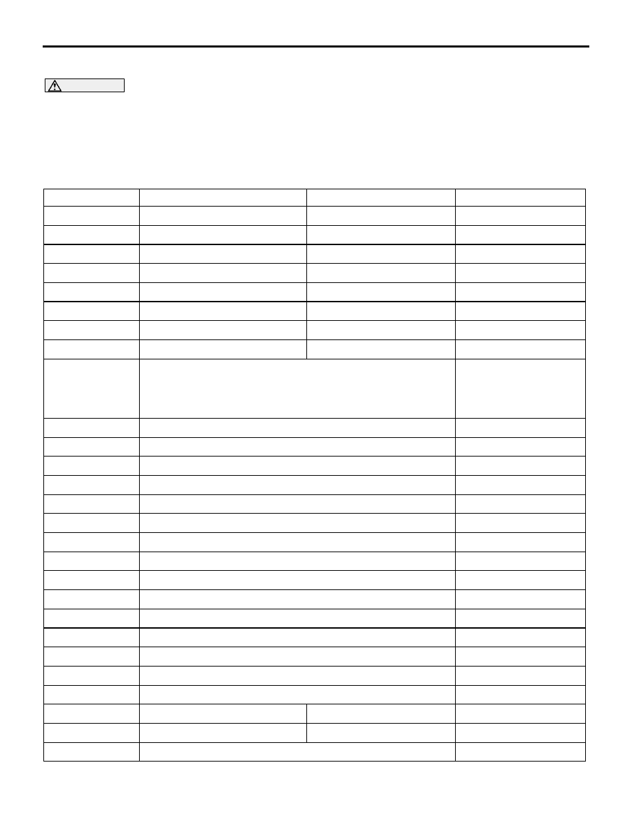
DIAGNOSTIC TROUBLE CODE CHART

M1352011300601

CAUTION

During diagnosis, a DTC code associated with 
another system may be set when the ignition 
switch is turned on with connector(s) discon-
nected. On completion, confirm all systems for 
DTCs. If DTC code(s) are set, erase them all.
Follow the inspection chart that is appropriate for the 
diagnostic trouble code.

DTC

INSPECTION ITEM

DIAGNOSTIC CONTENT

REFERENCE PAGE

C1200

Front right wheel speed sensor

Open circuit or short circuit

P.35B-10

C1201

Front right wheel speed sensor

Abnormal output signal

P.35B-26

C1205

Front left wheel speed sensor

Open circuit or short circuit

P.35B-10

C1206

Front left wheel speed sensor

Abnormal output signal

P.35B-26

C1210

Rear right wheel speed sensor

Open circuit or short circuit

P.35B-10

C1211

Rear right wheel speed sensor

Abnormal output signal

P.35B-26

C1215

Rear left wheel speed sensor

Open circuit or short circuit

P.35B-10

C1216

Rear left wheel speed sensor

Abnormal output signal

P.35B-26

C1225

Deviation between wheel speeds

P.35B-40

 or refer to the 

above appropriate 
abnormal output sensor 
signal

P.35B-26


C1226

ABS front right (FR) inlet solenoid valve

P.35B-41

C1231

ABS front right (FR) outlet solenoid valve

P.35B-41

C1236

ABS front left (FL) inlet solenoid valve

P.35B-41

C1241

ABS front left (FL) outlet solenoid valve

P.35B-41

C1246

ABS rear right (RR) inlet solenoid valve

P.35B-41

C1251

ABS rear right (RR) outlet solenoid valve

P.35B-41

C1256

ABS rear left (RL) inlet solenoid valve

P.35B-41

C1261

ABS rear left (RL) outlet solenoid valve

P.35B-41

C1266

Motor pump system (seizure)

P.35B-48

C1273

Motor relay (drive circuit) problem (stays off)

P.35B-48

C1274

Motor relay (drive circuit) problem (stays on)

P.35B-48

C1276

Valve relay malfunction

P.35B-56

C1278

Valve relay problem (stays off)

P.35B-56

C1279

Valve relay problem (stays on)

P.35B-56

C1607

ABS-ECU malfunction

P.35B-62

C1860

Power supply system

Abnormal rise in voltage

P.35B-63

C1861

Power supply system

Abnormal drop in voltage

P.35B-63

U1073

CAN-Bus off

P.35B-69

ANTI-LOCK BRAKING SYSTEM (ABS) DIAGNOSIS

ANTI-LOCK BRAKING SYSTEM (ABS)

35B-10

NOTE: Since the ABS system is controlled with the same ABS/TCL-ECU used to control the TCL system, the 
codes (with a *) used only for the ABS system also appear. 

The inspection contents for the codes (with a *) used only for the TCL system do not described in this group.

DIAGNOSTIC TROUBLE CODE PROCEDURES

DTC C1200/C1205/C1210/1215 Wheel Speed Sensor (Open circuit or short circuit)

CAUTION

• Wheel speed sensor wires/ wiring are not to 

be interchanged, as this could destroy the 
sensor.

• Never apply external voltage (e.g. battery volt-

age) to sensors. Excessively high voltages or 
current can lead to failures.

NOTE: If the ABS-8 ECU or the active wheel 
speed sensor are disconnected, or if the wiring is 

an open/ short circuit, the ABS 8 ECU will shut 
off power supply to the respective wheel speed 
sensor. All other wheel speed sensors will oper-
ate normally. To restore the power supply, the 
ignition switch must be turned to the "OFF" posi-
tion then to the "ON" position again.

U1100*

CAN communications system time out error engine related 
data

GROUP 13D, 
Diagnostic Trouble Code 
Procedures 

13A-527

U1101*

CAN communications system time out error A/T related data

GROUP 54C, 
Diagnostic Trouble Code 
Procedures 

U1400*

CAN invalid signal Accelerator Position (Dynamic range error 
APS)

GROUP 13D, 
Diagnostic Trouble Code 
Procedures 

13A-515

U1415

CAN invalid signal Gear Position

GROUP 23A    
Diagnostic Trouble Code 
Chart 

P.23A-34

DTC

INSPECTION ITEM

DIAGNOSTIC CONTENT

REFERENCE PAGE

35DB090A

A

ANTI-LOCK BRAKING SYSTEM (ABS) DIAGNOSIS

ANTI-LOCK BRAKING SYSTEM (ABS)

35B-11

CAUTION

If there is any problem in the CAN bus lines, an 
incorrect diagnostic trouble code may be set. 
Diagnose the CAN bus lines before the DTC 
(Refer to GROUP 54C, Trouble code diagno-
sis

P.54C-13

).

.

CIRCUIT OPERATION

• Active wheel speed sensors have been installed, 

that produce changes of current flow through the 
wheel speed sensor circuit which is influenced by 
the reluctor ring fitted to the wheel hub.

• Active wheel speed sensors have a constant 

incoming power supply on one wire and return a 
signal on the other wire

• The advantage of the active wheel speed sensor 

is that  there is always a signal until the wheel 
has stopped. As the wheel speeds up or slows 
down, the frequency will change where the ampli-
tude of the signal will remain constant.

• A Hall switch and magnet assembly is contained 

within the sensor.

• As the tooth on the reluctor approaches the sen-

sor, the magnetic circuit is completed therefore 
turning on the Hall switch. As the tooth departs 
the sensor, the Hall switch will turn off.

• The output waveform displayed on the oscillo-

scope will be a square wave, (between signal 
wire and ground).

• The ABS hydraulic unit modulates the amount of 

braking force individually applied to each wheel 
cylinder.

.

ABS DTC SET CONDITIONS

The ABS-ECU monitors voltage fluctuation in each 
wheel speed sensor circuit. If the ECU detects a 
short or open circuit in the circuit, it will set a diag-
nostic trouble code.

.

WHEEL SPEED SENSOR AIR GAP:

• Sensor air gap:   (0.2mm - 0.85mm).

.

ANTI-LOCK BRAKING SYSTEM (ABS) DIAGNOSIS

ANTI-LOCK BRAKING SYSTEM (ABS)

35B-12

TROUBLESHOOTING HINTS (The most 
likely causes for these DTCs are to set 
are:)

Current trouble

• Malfunction of the wheel speed sensor

• Damaged wiring harness or connector

• Malfunction of the hydraulic unit (integrated with 

ABS-ECU)

Past  trouble

• Carry out diagnosis with particular emphasis on 

connector(s) or wiring harness in wheel speed 
sensor circuit. For diagnosis procedures, refer to 
"How to cope with past trouble" (Refer to GROUP 
00, How to use Troubleshooting/Inspection Ser-
vice Points

P.00-16

).

Circuit drawings

• Refer to circuit diagrams GROUP-

90

• Refer to configuration diagrams GROUP-

80

.

DIAGNOSIS

Required Special Tools:

• MB991958: Diagnostic Tool (MUT-III Sub Assembly)

• MB991824: Vehicle Communication Interface (V.C.I.)

• MB991827: MUT-III USB Cable

• MB991910: MUT-III Main Harness A

• MB991222: Back-probing probe

• MB991219: Inspection test harness

.

STEP 1. Using diagnostic tool MB991958, diagnose the 
CAN bus line.

CAUTION

To prevent damage to diagnostic tool MB991958, always 
turn the ignition switch to the "LOCK" (OFF) position 
before connecting or disconnecting diagnostic tool 
MB991958.
(1) Connect diagnostic tool MB991958 to the data link 

connector.

(2) Turn the ignition switch to the "ON" position.
(3) Diagnose the CAN bus line.
(4) Turn the ignition switch to the "LOCK" (OFF) position.

Q: Is the CAN bus line found to be normal?

YES : Go to Step 3
NO :  Repair the CAN bus line (Refer to GROUP 54C, 

Diagnosis 

P.54C-15

). Then go to Step 2.

00DB076A

MB991910

DATA LINK

CONNECTOR

MB991824

MB991827


Content   ..  944  945  946  947   ..