Mitsubishi 380. Manual - part 927


  Index      Mitsubishi     Mitsubishi 380 - service repair manual 2005 year


Search            


Content   ..  925  926  927  928   ..


Mitsubishi 380. Manual - part 927


CLOCK DISPLAY

CHASSIS ELECTRICAL

54A-242

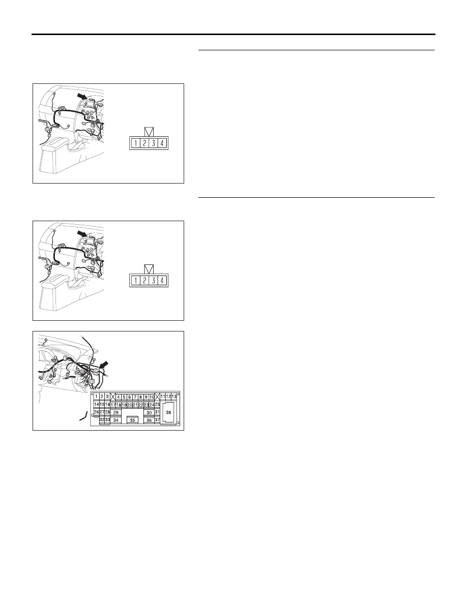
STEP 8. Check clock display unit  connector C-06 for 
loose, corroded or damaged terminals, or terminals 
pushed back in the connector.
Q: Is clock display unit  connector C-06 in good condition?

YES : Go to Step 9.
NO :  Repair or replace the connector. Refer to GROUP 

00E, Harness Connector Inspection 

P.00E-2

. The 

clock display unit  should work normally.

STEP 9. Check the wiring harness between C-06 (terminal 
3) and ignition switch (ACC).

NOTE: Also check intermediate connector C-29 for loose, cor-
roded, or damaged terminals, or terminals pushed back in the 
connector. If intermediate connector C-29 is damaged, repair or 
replace the wiring harness. Refer to GROUP 00E, Harness 
Connector Inspection 

P.00E-2

.

Q: Is the wiring harness between C-06 (terminal 3) and 

ignition switch (ACC) in good condition?
YES : 
There is no action to be taken.
NO :  Repair the wiring harness. The clock display unit  

should work normally.

16DB609A

CONNECTOR:  C-06

C-06

16DB609A

CONNECTOR:  C-06

C-06

52DB014A

CONNECTOR: C-29

CLOCK DISPLAY

CHASSIS ELECTRICAL

54A-243

STEP 10. Check the clock display unit illumination power 
supply circuit [headlamp switch (park, low or high)]. 
Measure the voltage at the clock display unit  connector 
C-06.
(1) Disconnect the clock display unit  connector C-06 and 

measure at the harness side.

(2) Turn the headlamp switch to "ON" position.

(3) Measure the voltage between terminal 2 and ground.

• The measured value should be approximately 12 volts 

(battery positive voltage).

Q: Does the measured voltage correspond with this range?

YES : Replace the clock display unit . The multi-centre 

display unit  should work normally.

NO :  Go to Step 11.

STEP 11. Check the clock display unit  connector C-06 for 
loose, corroded or damaged terminals, or terminals 
pushed back in the connector.
Q: Is clock display unit  connector C-06 in good condition?

YES : Go to Step 12.
NO :  Repair or replace the connector. Refer to GROUP 

00E, Harness Connector Inspection 

P.00E-2

. The 

clock display unit  should work normally.

16DB609A

CONNECTOR:  C-06

C-06

16DB613A

CONNECTOR C-06 

(HARNESS SIDE)

16DB609A

CONNECTOR:  C-06

C-06

CLOCK DISPLAY

CHASSIS ELECTRICAL

54A-244

STEP 12. Check the wiring harness between clock display 
unit  connector C-06 (terminal 2) and tail lamp relay and 
(fuse No.20) at relay box.

NOTE: Also check junction block connector C-211 and C-214 
for loose, corroded, or damaged terminals, or terminals pushed 
back in the connector. If junction block connector C-211 or 
C-214 is damaged, repair or replace the wiring harness. Refer 
to GROUP 00E, Harness Connector Inspection 

P.00E-2

.

Q: Is the wiring harness between multi-centre display unit  

connector C-06 (terminal 2) and tail lamp relay and (fuse 
No.20) at relay box in good condition?
YES : 
The procedure is complete.
NO :  Repair the wiring harness. The clock display unit  

should work normally.

16DB609A

CONNECTOR:  C-06

C-06

CLOCK DISPLAY

CHASSIS ELECTRICAL

54A-245

CLOCK DISPLAY

REMOVAL AND INSTALLATION

16DB614A

1

4

3

4

2

REMOVAL STEPS

1.

CONSOLE METER HOOD (REFER TO 
GROUP 52A, INSTRUMENT PANEL 
ASSEMBLY 

P.52A-4

.)

2.

CLOCK DISPLAY ASSEMBLY

3.

CLOCK DISPLAY

4.

CLOCK DISPLAY BRACKET

REMOVAL STEPS (Continued)


Content   ..  925  926  927  928   ..