Mitsubishi 380. Manual - part 776


  Index      Mitsubishi     Mitsubishi 380 - service repair manual 2005 year


Search            


Content   ..  774  775  776  777   ..


Mitsubishi 380. Manual - part 776


SRS AIR BAG DIAGNOSIS

SUPPLEMENTAL RESTRAINT SYSTEM (SRS)

52B-28

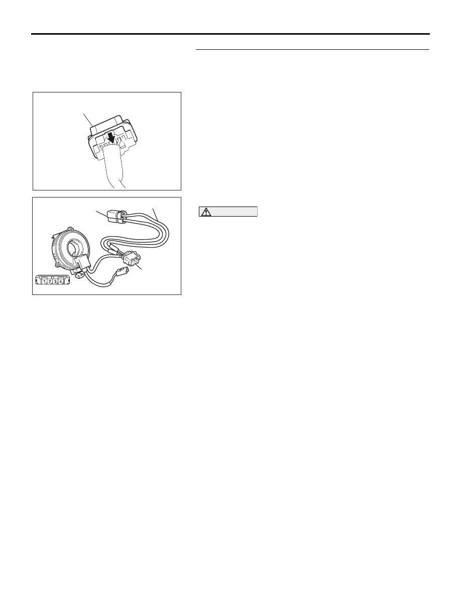
STEP 6. Check the driver's air bag module. (Using 
diagnostic tool MB991958, read the diagnostic trouble 
code.)
(1) Disconnect the negative battery terminal.
(2) Slide the outer housing of the clock spring side of driver’s 

air bag module connector C-305 in the arrow direction 
shown, and disconnect the connector.

(3) Connect special tool MB991865 to special tool MB991866.

CAUTION

Do not insert a test probe into the terminal from its front 
side directly as the connector contact pressure may be 
weakened.
(4) Insert special tool MB991866 into clock spring side of 

driver’s air bag module connector C-305 (terminal No.1 and 
2 ) by testprobe.

(5) Connect the negative battery terminal.
(6) Erase the diagnostic trouble code memory, and check the 

diagnostic trouble code.

Q:  Is DTC B1400  set?

YES : Go to Step 7.
NO :  Replace the driver's air bag module (Refer to 

P.52B-237

). Then go to Step 10. 

AC306561AC

OUTER HOUSING OF THE DRIVER'S 
AIR BAG MODULE CONNECTOR C-305

AC306758 AB

C-305 AIR BAG
MODULE
CONNECTOR

MB991865
(DUMMY RESISTOR : 3Ω)

MB991866 (RESISTOR 
HARNESS)

(REAR VIEW)

SRS AIR BAG DIAGNOSIS

SUPPLEMENTAL RESTRAINT SYSTEM (SRS)

52B-29

STEP 7. Check the clock spring. (Using diagnostic tool 
MB991958, read the diagnostic trouble code.)
(1) Disconnect the negative battery terminal.
(2) Disconnect the clock spring connector C-307.

(3) Connect special tool MB991865 to special tool MB991866.

CAUTION

Do not insert a test probe into the terminal from its front 
side directly, as the connector contact pressure may be 
weakened.
(4) Insert special tool MB991866 into clock spring harness side 

connector C-307 (terminal No.13 and 14 ) by testprobe.

(5) Connect the negative battery terminal.
(6) Erase the diagnostic trouble code memory, and check the 

diagnostic trouble code.

Q: Is DTC B1400  set?

YES : Go to Step 8.
NO :  Replace the clock spring (Refer to 

P.52B-237

). Then 

go to Step 10

52DB008A

C-307 (Y)

CONNECTOR: C-307

C-307 HARNESS

SIDE CONNECTOR

CLOCK

SPRING

11

12

13

14

AC306767

C-307 CLOCK SPRING
CONNECTOR

AB

MB991865

(DUMMY RESISTOR : 3Ω)

MB991866 (RESISTOR 

HARNESS)

1112 14

13

(REAR VIEW)

SRS AIR BAG DIAGNOSIS

SUPPLEMENTAL RESTRAINT SYSTEM (SRS)

52B-30

STEP 8. Check the driver’s air bag module circuit. Measure 
the resistance at SRS-ECU connector C-121.
(1) Disconnect SRS-ECU connector C-121.

DANGER

To prevent the air bag from deploying unintentionally, 
disconnect clock spring connector C-307 to short the 
squib circuit.

(2) Disconnect clock spring connector C-307.

CAUTION

Insert an insulator such as a cable tie to a depth of 4mm 
(0.16 inch) or more, otherwise the short spring will not be 
released.
(3) Insert a cable tie [3 mm (0.12 inch) wide, 0.5 mm (0.02 inch) 

thick] between terminals 28, 27  and the short spring to 
release the short spring.

CAUTION

Do not insert a test probe into the terminal from its front 
side directly as the connector contact pressure may be 
weakened.
(4) Check for continuity between C-121 harness side connector 

terminals 28 and 27 .
It should be open circuit.

Q: Does continuity exist? 

YES : Erase the diagnostic trouble code memory, and check 

the diagnostic trouble code. If DTC B1400  set, 
replace the SRS-ECU (Refer to 

P.52B-234

). Then go 

to Step 10.

NO :  Go to Step 9. 

24DB062A

CONNECTOR: C-121

C-121 (Y)

SRS-ECU

42

31

38

27

21

41

28

39

22

30

25

47

36

33

44

34

45

37

48

26

29

23

40

32

43

35

46

24

B

A

C-121

INSTRUMENT

HARNESS

CONNECTOR

(REAR VIEW)

52DB008A

C-307 (Y)

CONNECTOR: C-307

C-307 HARNESS

SIDE CONNECTOR

CLOCK

SPRING

11

12

13

14

AC308144

SECTION
A - A

C-121 HARNESS SIDE 
CONNECTOR
(FRONT VIEW)

CABLE TIE

SHORT SPRING

4 mm OR MORE

TERMINAL

A

AB

A

<1ST SQUIB>

AC308141

SECTION
A - A

C-121 HARNESS SIDE 
CONNECTOR
(FRONT VIEW)

CABLE TIE

SHORT SPRING

4 mm OR MORE

TERMINAL

AB

<2ND SQUIB>

A

A

SRS AIR BAG DIAGNOSIS

SUPPLEMENTAL RESTRAINT SYSTEM (SRS)

52B-31

STEP 9. Check the harness for short circuit between 
SRS-ECU connector C-121 (terminal No.28 and 27 ) and 
clock spring connector C-307 (terminal No.13 and 14 ).
Q: Are harness wires between SRS-ECU connector C-121 

(terminal No.28 and 27 ) and clock spring connector 
C-307 (terminal No.13 and 14 ) in good condition?
YES : 
Go to Step 10.
NO :  Replace the harness wires between SRS-ECU 

connector C-121 and clock spring connector C-307. 
Then go to Step 10.

STEP 10. Recheck for diagnostic trouble code.
Check again if the DTC is set.
(1) Erase the DTC.
(2) Turn the ignition switch to the "ON" position.
(3) Check if the DTC is set.
(4) Turn the ignition switch to the "LOCK" (OFF) position.

Q: Is DTC B1400  set?

YES : Return to Step 1.
NO :  The procedure is complete.

52DB008A

C-307 (Y)

CONNECTOR: C-307

C-307 HARNESS

SIDE CONNECTOR

CLOCK

SPRING

11

12

13

14

24DB062A

CONNECTOR: C-121

C-121 (Y)

SRS-ECU

42

31

38

27

21

41

28

39

22

30

25

47

36

33

44

34

45

37

48

26

29

23

40

32

43

35

46

24

B

A

C-121

INSTRUMENT

HARNESS

CONNECTOR

(REAR VIEW)

00DB076A

MB991910

DATA LINK

CONNECTOR

MB991824

MB991827


Content   ..  774  775  776  777   ..