Mitsubishi 380. Manual - part 673


  Index      Mitsubishi     Mitsubishi 380 - service repair manual 2005 year


Search            


Content   ..  671  672  673  674   ..


Mitsubishi 380. Manual - part 673


DIAGNOSIS

CONTROLLER AREA NETWORK (CAN)

54C-103

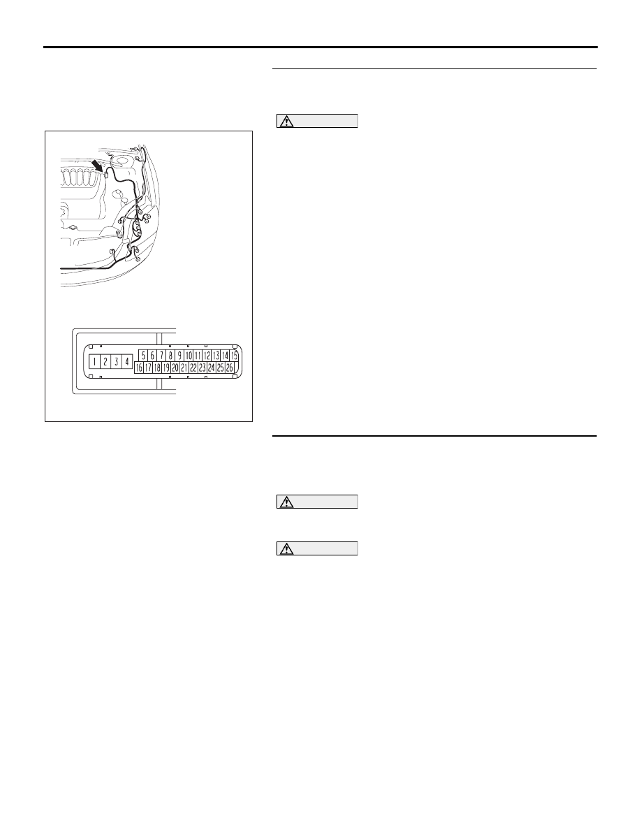
STEP 23. Check ABS-ECU connector A-02 for loose, 
corroded or damaged terminals, or terminals pushed back 
in the connector.

CAUTION

The strand end of the twisted wire should be within 10 cm 
(4 inches) from the connector. For details refer to 

P.54C-4

.

Q: Is ABS-ECU connector A-02 in good condition?

YES : Go to Step 24.
NO :  Repair the damaged parts.

STEP 24. Check the CAN_H line (communication line only) 
between intermediate connector C-29 and ABS-ECU 
connector for a short to the power supply. Measure the 
voltage at intermediate connector C-29.

CAUTION

A digital multimeter should be used. For details refer to 

P.54C-4

.

CAUTION

The test wiring harness should be used. For details refer to 

P.54C-4

.

16DB402A

A-02 (GR)

CONNECTOR: A-02 

A-02 HARNESS CONNECTOR:

DIAGNOSIS

CONTROLLER AREA NETWORK (CAN)

54C-104

(1) Disconnect intermediate connector C-29 and ABS-ECU 

connector A-02, and measure the voltage at the male side 
of intermediate connector C-29 (at front wiring harness 
side).

(2) Turn the ignition switch to the "ON" position.

(3) Measure the voltage between intermediate connector 

terminal 11 and body ground.

OK: 1.0 V or less

CAUTION

Strictly observe the specified wiring harness repair proce-
dure. For details refer to 

P.54C-5

.

Q: Does the voltage measure 1.0 V or less?

YES : If the voltage measures 1.0 V or less, go to Step 25.
NO :  If the voltage measures more than 1.0 V, repair the 

wiring harness between intermediate connector C-29 
and ABS-ECU connector.

16DB402A

A-02 (GR)

CONNECTOR: A-02 

A-02 HARNESS CONNECTOR:

AC209365

2 3

27

32

28

33

16

15

4 5

19

18

29

17

34

7 8

35

22

21

9 10

30

36

31

37

25

24

23

6

20

1

14

26

11

13

12

38

AC209365

MALE SIDE: C-29

TEST 
HARNESS

FP

DIAGNOSIS

CONTROLLER AREA NETWORK (CAN)

54C-105

STEP 25. Check the CAN_H line (communication line only) 

between the A/T-ECU connector and ABS-ECU connector 

for a short to the power supply. Measure voltage at 

A/T-ECU connector B-19.

• Refer to circuit diagrams GROUP-

90

• Refer to configuration diagrams GROUP-

80

CAUTION

A digital multimeter should be used. For details refer to 

P.54C-4

.

CAUTION

The test wiring harness should be used. For details refer to 

P.54C-4

.

(1) Disconnect A/T-ECU connector B-19 and ABS-ECU 

connector A-02, and measure the voltage at the harness 
side of A/T-ECU connector B-19.

(2) Turn the ignition switch to the "ON" position.

16DB480A

COVER

ENGINE
CONTROL
UNIT

AIR
CLEANER

A/T
CONTROL
UNIT

16DB402A

A-02 (GR)

CONNECTOR: A-02 

A-02 HARNESS CONNECTOR:

DIAGNOSIS

CONTROLLER AREA NETWORK (CAN)

54C-106

(3) Measure the voltage between A/T-ECU connector terminal 

13 and body ground.

OK: 1.0 V or less

CAUTION

Strictly observe the specified wiring harness repair proce-
dure. For details refer to 

P.54C-5

.

Q: Does the voltage measure 1.0 V or less?

YES : If the voltage measures 1.0 V or less, go to Step 26.
NO :  If the voltage measures more than 1.0 V, repair the 

wiring harness between ENGINE-ECU connector and 
ABS-ECU connector.

STEP 26. Check the CAN_H line inside the ABS-ECU for a 
short to the power supply. Measure the voltage at 
ABS-ECU connector A-02.

CAUTION

A digital multimeter should be used. For details refer to 

P.54C-4

.

CAUTION

The test wiring harness should be used. For details refer to 

P.54C-4

.

(1) Disconnect ABS-ECU connector A-02.

16DB481A

 B-19

TEST 
HARNESS

16DB402A

A-02 (GR)

CONNECTOR: A-02 

A-02 HARNESS CONNECTOR:


Content   ..  671  672  673  674   ..