Mitsubishi 380. Manual - part 616


  Index      Mitsubishi     Mitsubishi 380 - service repair manual 2005 year


Search            


Content   ..  614  615  616  617   ..


Mitsubishi 380. Manual - part 616


MULTIPORT FUEL INJECTION (MPI) DIAG

MULTIPORT FUEL INJECTION (MPI)

13A-556

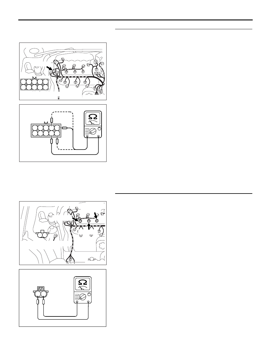
STEP 8. Check the right bank injector resistance at 
intermediate connector B-32.
(1) Disconnect the intermediate connector B-32.

(2) Measure the resistance between each male connector side 

terminal.

a. Measure the resistance between terminal No. 9 and No. 

5 at No. 1 cylinder injector.

b. Measure the resistance between terminal No. 9 and No. 

10 at No. 3 cylinder injector.

c. Measure the resistance between terminal No. 9 and No. 

4 at No. 5 cylinder injector.

• Resistance should be between 10.5 and 13.5 ohms [at 

20

°C (68°F)].

Q: Is the measured resistance between 10.5 and 13.5 ohms 

[at 20

°C (68°F)]?

YES : Go to Step 11.
NO :  Go to Step 9.

STEP 9. Check the right bank injector.
(1) Remove the intake manifold.
(2) Disconnect the right bank injector connector, which 

deviates from the standard value at Step 7.

(3) Measure the resistance between injector side connector 

terminal No. 1 and No. 2.

Standard value: 10.5 

 13.5 ohms [at 20°C (68°F)]

Q: Is the measured resistance between 10.5 and 13.5 ohms 

[at 20

°C (68°F)]?

YES : Go to Step 10.
NO :  Replace the injector. Then confirm that the 

malfunction symptom is eliminated.

AK303053

3

4

5

8

9

1

2

6

7

10

CONNECTOR: B-32

HARNESS CONNECTOR:

COMPONENT SIDE

AB

B-32 (B)

1 2 3
6 7 8

4 5
9 10

AK203093

B-32 

INTERMEDIATE

CONNECTOR

AB

AK303055

M

1

2

CONNECTOR: B-01, B-03, B-04

AB

B-01 (GR)

B-03 (GR)

B-04 (GR)

HARNESS CONNECTOR:

COMPONENT SIDE

AK000559

2

1

INJECTOR SIDE
CONNECTOR

AB

MULTIPORT FUEL INJECTION (MPI) DIAG

MULTIPORT FUEL INJECTION (MPI)

13A-557

STEP 10. Check harness connector B-03 or B-04 or B-01 at 
right bank injector for damage.
(1) Check the injector connector, which deviates from the 

standard value at Step 9.

Q: Is the harness connector in good condition?

YES : Repair harness wire between injector intermediate 

connector and right bank injector connector because 
of harness damage. Then confirm that the 
malfunction symptom is eliminated.

NO :  Repair or replace it. Refer to GROUP 00E, Harness 

Connector Inspection 

P.00E-2

. Then confirm that the 

malfunction symptom is eliminated.

STEP 11. Check harness connector B-32 at intermediate 
connector for damage.
Q: Is the harness connector in good condition?

YES : Go to Step 12.
NO :  Repair or replace it. Refer to GROUP 00E, Harness 

Connector Inspection 

P.00E-2

. Then confirm that the 

malfunction symptom is eliminated.

STEP 12. Check harness connector B-27, B-26, B-30 at left 
bank injector for damage.
Q: Is the harness connector in good condition?

YES : Go to Step 13.
NO :  Repair or replace it. Refer to GROUP 00E, Harness 

Connector Inspection 

P.00E-2

.Then confirm that the 

malfunction symptom is eliminated.

AK303055

M

1

2

CONNECTOR: B-01, B-03, B-04

AB

B-01 (GR)

B-03 (GR)

B-04 (GR)

HARNESS CONNECTOR:

COMPONENT SIDE

AK303053

3

4

5

8

9

1

2

6

7

10

CONNECTOR: B-32

HARNESS CONNECTOR:

COMPONENT SIDE

AB

B-32 (B)

AK303075

M

1

2

CONNECTOR: B-26, B-27, B-30

B-30 (GR)

B-27 (GR)

B-26 (GR)

HARNESS CONNECTOR:

COMPONENT SIDE

AB

MULTIPORT FUEL INJECTION (MPI) DIAG

MULTIPORT FUEL INJECTION (MPI)

13A-558

STEP 13. Check harness connector B-20 at ENGINE-ECU 
for damage.
Q: Is the harness connector in good condition?

YES : Go to Step 14.
NO :  Repair or replace it. Refer to GROUP 00E, Harness 

Connector Inspection 

P.00E-2

. Then confirm that the 

malfunction symptom is eliminated.

16DB400A

COVER

ENGINE

CONTROL

UNIT

AIR

CLEANER

MULTIPORT FUEL INJECTION (MPI) DIAG

MULTIPORT FUEL INJECTION (MPI)

13A-559

STEP 14. Check for harness damage between injector 
connector and ENGINE-ECU connector.

a. Check the harness wire between injector connector 

B-01 (terminal No. 2) and ENGINE-ECU connector B-20 
(terminal No. 03) at No. 1 cylinder injector.

b. Check the harness wire between injector connector 

B-30 (terminal No. 2) and ENGINE-ECU connector B-20 
(terminal No. 04) at No. 2 cylinder injector.

c. Check the harness wire between injector connector 

B-03 (terminal No. 2) and ENGINE-ECU connector B-20 
(terminal No. 34) at No. 3 cylinder injector.

d. Check the harness wire between injector connector 

B-27 (terminal No. 2) and ENGINE-ECU connector B-20 
(terminal No. 35) at No. 4 cylinder injector.

e. Check the harness wire between injector connector 

B-04 (terminal No. 2) and ENGINE-ECU connector B-20 
(terminal No. 16) at No. 5 cylinder injector.

f. Check the harness wire between injector connector 

B-26 (terminal No. 2) and ENGINE-ECU connector B-20 
(terminal No. 17) at No. 6 cylinder injector.

Q: Is the harness wire in good condition?

YES : Check the following items, and repair or replace the 

defective items.

a. Check the ignition coil and spark plugs.
b. Check if the injectors are clogged.

c. Check compression pressure.

d. Check fuel lines for clogging.
e. Check if the foreign materials (water, 

kerosene, etc.) got into fuel.

Then confirm that the malfunction symptom is 

eliminated.

NO :  Repair it. Then confirm that the malfunction symptom 

is eliminated.

STEP 15. Check injector is insulated from earth.
(1) Measure the resistance between each injector housing and 

earth.

Q: Is there no continuity?

YES : ok.
NO :  Repair or replace injector. Then confirm that the 

malfunction symptom is eliminated.

AK303235

M

1

2

AB

B-30 (GR)

B-04 (GR)

B-01 (GR)

B-27 (GR)

B-03 (GR)

B-26 (GR)

CONNECTOR: B-01, B-03, B-04, B-26,B-27,

                         B-30

HARNESS CONNECTOR:

COMPONENT SIDE

16DB400A

COVER

ENGINE

CONTROL

UNIT

AIR

CLEANER

03DB230A

INJECTOR 
HOUSING


Content   ..  614  615  616  617   ..