Mitsubishi 380. Manual - part 374
AUTOMATIC TRANSMISSION DIAGNOSIS
AUTOMATIC TRANSMISSION
23A-36
DIAGNOSTIC TROUBLE CODE PROCEDURES
(P0713): Transmission Fluid Temperature Sensor System (Open Circuit)
.
CIRCUIT OPERATION
• The A/T-ECU connector B-22 (terminal 6) applies
5 volts to the transmission fluid temperature sen-
sor output terminal (terminal 1).
• The transmission fluid temperature sensor circuit
is grounded to the A/T-ECU connector B-22 (ter-
minal 12).
• When the transmission fluid temperature is cold,
the transmission fluid temperature sensor resis-
tance is high. When the transmission fluid tem-
perature is hot, the transmission fluid
temperature sensor resistance is low.
.
DTC SET CONDITIONS
Check Conditions
• Engine speed: 1,000 r/min or more.
• Output speed: 1,000 r/min or more.
• Accumulated time in above condition: 10 min-
utes.
Judgement Criteria
• Transmission fluid temperature sensor voltage:
4.5 volts or more. (1 second)
.
OBD-II DRIVE CYCLE PATTERN
Start the engine, drive at 60 km/h or more for 15 min-
utes in total.
.
TROUBLESHOOTING HINTS (THE MOST
LIKELY CAUSES FOR THIS CODE TO BE
SET ARE:)
• Malfunction of the transmission fluid temperature
sensor circuit
• Damaged harness or connector
• Malfunction of the A/T-ECU
Circuit drawings
• Refer to circuit diagrams GROUP-
• Refer to configuration diagrams GROUP-
• Refer to component locations GROUP-
DIAGNOSIS
Required Special Tool:
• MB991958: Diagnostic Tool (MUT-III Sub Assembly)
• MB991824: V.C.I.
• MB991827: MUT-III USB Cable
• MB991910: MUT-III Main Harness A
16DB564A
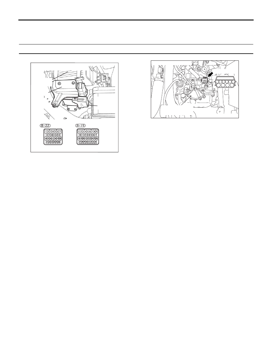
COVER
AIR
CLEANER
A/T
CONTROL
UNIT
CONNECTORS: B-19, B-22
AC306322
CONNECTOR: B-108
B-108 (GR)
AC
TRANSMISSION
RANGE SWITCH
2
7
1
8
3
9
4
6
10
5