Mitsubishi 380. Manual - part 356
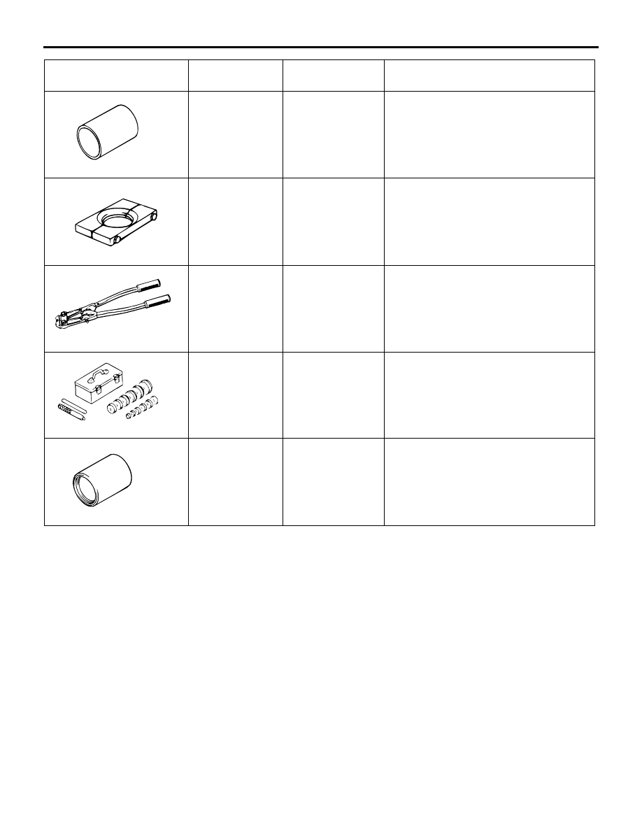
SPECIAL TOOLS
FRONT AXLE
26-6
MB991172
Inner shaft
installer base
−
Press-fitting of the inner shaft
MB991248
Inner shaft
remover
MD998348-01 or
General service
tool
Removal of the inner shaft
MB991561
Boot band
crimping tool
MB991561
BJ boot (resin boot) band installation
MB990925
Bearing and oil
seal installer set
MB990925-01 or
General service
tool
• Removal and installation of the
center bearing
• Press-fitting of the dust seal outer,
inner
MB990890
Rear suspension
bushing base
MB990890-01
Press-fitting of the dust seal outer, inner
TOOL
TOOL NUMBER
AND NAME
SUPERSESSION APPLICATION
MB991248
MB991561
MB990925
MB990890