Mitsubishi 380. Manual - part 226


  Index      Mitsubishi     Mitsubishi 380 - service repair manual 2005 year


Search            


Content   ..  224  225  226  227   ..


Mitsubishi 380. Manual - part 226


HARNESS CONNECTOR INSPECTION

GENERAL <ELECTRICAL>

00E-2

HARNESS CONNECTOR INSPECTION

M1001003900201

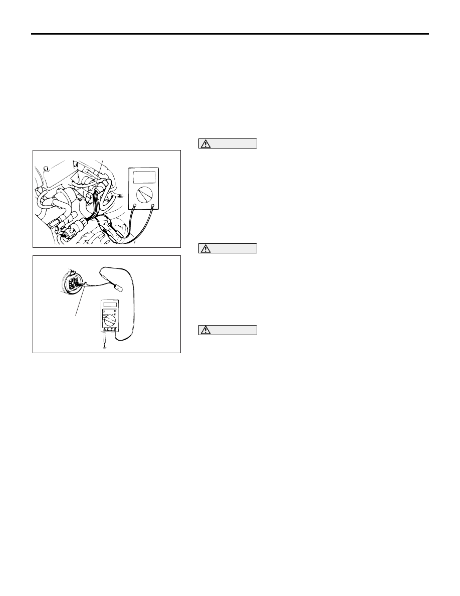
CONNECTOR CONTINUITY AND VOLTAGE TEST

Required Special Tools:

• MB991219: Test Harness Set

• MD998459: Test Harness

Follow the steps below to avoid causing poor connector contact 
and/or reduced waterproof performance of connectors when 
checking continuity and/or voltage at waterproof connectors.

CAUTION

Never backtest probe a waterproof connector. Backprob-
ing a connector may cause the terminals to corrode, dete-
riorating circuit performance.
1. If the circuit to be checked is a closed state, use a special 

tool like MD998459. 

CAUTION

Forcing the test probe into the terminal may open the ter-
minal, causing intermittent or poor contact and creating an 
open circuit.
2. If the connector is disconnected for checking and the facing 

part is the female pin side, use an appropriate male terminal 
for checking the contact pressure of connector pins (like 
MB991219).

CAUTION

Do not simultaneously contact more than one terminal 
with the test probe. Contacting two or more terminals at 
the same time may damage a circuit, possibly to the point 
of starting an electrical fire.
3. If the facing part is the male pin side, either carefully touch 

the test probe to the pin so it does not accidently contact 
other pins, or use an appropriate female terminal.

HOW TO DIAGNOSE

HOW TO DIAGNOSE

M1001004300086

The most important point in troubleshooting is to 
determine "Probable Cause." Once the probable 
causes are determined, parts to be checked can be 
limited to those associated with such probable 
causes. The determination of the probable causes 
must be based on a theory and be supported by facts 
and must not be based on intuition only.

AC000014

AB

MD998459

AC000015

AB

MB991219

HOW TO DIAGNOSE

GENERAL <ELECTRICAL>

00E-3

TROUBLESHOOTING STEPS

M1001004400049

If an attempt is made to solve a problem without going through correct steps for troubleshooting, the symp-
toms could become more complicated, resulting in failure to determine the causes correctly and making 
incorrect repairs. The four steps below should be followed in troubleshooting.

INFORMATION FOR DIAGNOSIS

M1001004500132

This manual contains the harness diagrams as well as the individual circuit drawings, operational explana-
tions, and troubleshooting hints for each component. The information is presented in the following manner:

1. Connector diagrams show the connector 

positions, etc., on the actual vehicle as well as the 
harness path.

2. Circuit diagrams show the configuration of the 

circuit with all switches in their normal positions.

3. Operational explanations include circuit drawings 

of current flow when the switch is operated and 
how the component reacts.

4. Troubleshooting hints include numerous 

examples of problems which might occur, traced 
backward in a common-sense manner to the 
origin of the trouble. Problems whose origins may 
not be found in this manner are pursued through 
the various system circuits.

NOTE:  Components of MPI, ETACS, etc. with ECU do not include 3 and 4 above. For this information, refer 
to a relevant group which includes details of these components.

00DB087A

3

Checking of Parts Associated with

Probable Causes and Determination

of Faulty Parts

2 Determination of Probable Causes

4 Confirmation

Observe the symptom carefully. Check if there are also 

other problems.

In determining the probable causes, it is necessary to 

study the wiring diagram to understand the circuit as a 

system. Knowledge of switches, relays and other parts is 

necessary for accurate analysis. The causes of similar 

problems in the past must be taken into account.

Troubleshooting is carried out by making step-by-step 

checks until the cause is found.

After the problems are corrected, be sure to check that the

system operates correctly. 

1 Observation of Problem Symptoms

HOW TO DIAGNOSE

GENERAL <ELECTRICAL>

00E-4

INSPECTION

M1001004600139

1. Sight and sound checks

Check relay operation, blower motor rotation, light 
illumination, etc. Listen for a "click" when some relay covers 
are pushed down.

2. Simple checks

For example, if a headlight does not come on and a faulty 
fuse or poor grounding is suspected, replace the fuse with a 
new one. Or use a jumper wire to ground the light to the 
body. Determine which part(s) is/are responsible for the 
problem.

3. Checking with instruments

Use an appropriate instrument in an adequate range and 
read the indication correctly.

ACX00936 AB

CLICK

ACX00937

ACX00938AB

SELECTOR KNOB

POINTER

HOW TO DIAGNOSE

GENERAL <ELECTRICAL>

00E-5

INSPECTION INSTRUMENTS

M1001004700040

For inspection, use the following instruments:

CAUTION

Never use a test light for checking ECU-related circuits or 
ECUs.
1. Test light

A test light consists of a 12V bulb and lead wires. It is used 
to check voltages or short circuits.

2. Self-powered test light

A self-powered test light consists of a bulb, battery and lead 
wires connected in series. It is used to check continuity or 
grounding.

CAUTION

Never use a jumper wire to connect a power supply 
directly to a load.
3. Jumper wire

A jumper wire is used to close an open circuit. 

4. Voltmeter

A voltmeter is used to measure the circuit voltage. Normally, 
the positive (red lead) test probe is applied to the point of 
voltage measurement and the negative (black lead) test 
probe to the body ground. Use a digital voltmeter to check 
for voltage drop before or after a component.

ACX00939

ACX00940

ACX00941

ACX00942AB

RED LEAD WIRE

POWER LINE

BLACK LEAD WIRE

GROUND


Content   ..  224  225  226  227   ..