Mitsubishi 380. Manual - part 189


  Index      Mitsubishi     Mitsubishi 380 - service repair manual 2005 year


Search            


Content   ..  187  188  189  190   ..


Mitsubishi 380. Manual - part 189


AUTO A/C DIAGNOSIS

HEATER, AIR CONDITIONING AND VENTILATION

55-52

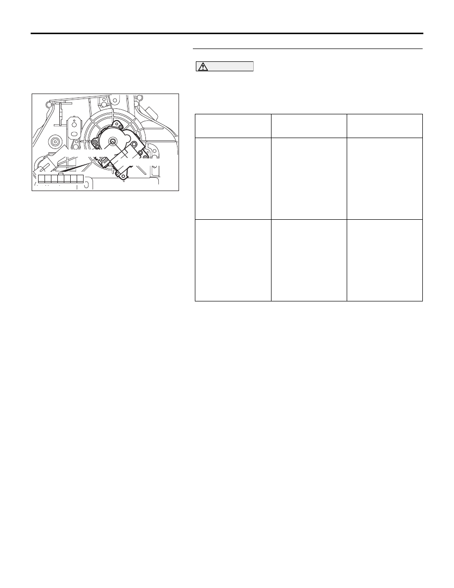
STEP 6. Check the mode selection damper control motor.

CAUTION

Do not apply battery voltage when the damper is in the 
FACE or DEF position.
Check the mode selection damper control motor by the follow-
ing procedures.

Q: Is the mode selection damper control motor in good 

condition?
YES : 
Go to Step 7.
NO :  Replace the mode selection damper control motor 

and potentiometer. Then go to Step 7.

LEVER POSITION BATTERY 

CONNECTION

LEVER 
OPERATION

At the FACE 
position

• Connect 

terminal 2 to the 
positive battery 
terminal

• Connect 

terminal 1 to the 
negative battery 
terminal

The lever moves 
from the FACE 
position to the DEF 
position

At the DEF position

• Connect 

terminal 1 to the 
positive battery 
terminal

• Connect 

terminal 2 to the 
negative battery 
terminal

The lever moves 
from the DEF 
position to the 
FACE position

25DB066A

FACE POSITION

DEF POSITION

1 2

4

3

5

7

6

AUTO A/C DIAGNOSIS

HEATER, AIR CONDITIONING AND VENTILATION

55-53

STEP 7. Recheck for diagnostic trouble code.
Check again if the DTC is set.
(1) Connect diagnostic tool  to the data link connector
(2) Turn the ignition switch to the "ON" position.
(3) Check if the DTC is set.
(4) Turn the ignition switch to the "LOCK" (OFF) position.

Q: Is the check result satisfactory?

YES : The procedure is complete.
NO :  Return to Step 1.

00DB076A

MB991910

DATA LINK

CONNECTOR

MB991824

MB991827

AUTO A/C DIAGNOSIS

HEATER, AIR CONDITIONING AND VENTILATION

55-54

DTC U1073: Bus Off

CAUTION

If DTC U1073 is set in the A/C-ECU, diagnose the 
CAN main bus line.

CAUTION

Whenever the ECU is replaced, ensure that the 
communication circuit is normal.

.

TROUBLE JUDGMENT

DTC U1073 will be stored when the A/C-ECU ceases 
CAN communication (bus off) and then resumes the 
communication when the ignition switch is turned to 
the "LOCK" (OFF) position.

.

TECHNICAL DESCRIPTION (COMMENT) 

The wiring harness wire or connectors may have 
loose, corroded, or damage terminals, or terminals 
pushed back in the connector, or the A/C-ECU may 
be defective.

.

TROUBLESHOOTING HINTS

• Defective connector(s) or wiring harness

• Malfunction of the A/C-ECU.

• Refer to component locations GROUP-

70

• Refer to configuration diagrams GROUP-

80

• Refer to circuit diagrams GROUP-

90

DIAGNOSIS

Required Special Tools:

• MB991223: Harness Set

•  : Diagnostic Tool (MUT-III Sub Assembly)

• MB991824: V.C.I.

• MB991827: USB Cable

• MB991910: Main Harness A

STEP 1. Using diagnostic tool , diagnose the CAN bus line.

CAUTION

To prevent damage to diagnostic tool (MUT-III), always turn 
the ignition switch to the "LOCK" (OFF) position before 
connecting or disconnecting diagnostic tool (MUT-III).
(1) Connect diagnostic tool  to the data link connector.
(2) Turn the ignition switch to the "ON" position.
(3) Diagnose the CAN bus line.
(4) Turn the ignition switch to the "LOCK" (OFF) position.

Q: Is the CAN bus line found to be normal?

YES : Go to Step 2.
NO :  Repair the CAN bus lines (Refer to GROUP 54C, 

precautions on how to repair the can bus lines 

P.54C-5

).

00DB076A

MB991910

DATA LINK

CONNECTOR

MB991824

MB991827

AUTO A/C DIAGNOSIS

HEATER, AIR CONDITIONING AND VENTILATION

55-55

STEP 2. Recheck for diagnostic trouble code.
Check again if the DTC is set.
(1) Connect diagnostic tool  to the data link connector
(2) Turn the ignition switch to the "ON" position.
(3) Check if the DTC is set.
(4) Turn the ignition switch to the "LOCK" (OFF) position.

Q: Is the check result satisfactory?

YES : There is an intermittent malfunction such as poor 

engaged connector(s) or open circuit (Refer to 
GROUP 00, How to Use Troubleshooting/Inspection 
Service Points 

− How to Cope with Intermittent 

Malfunctions 

P.00-14

.)

NO :  Replace the A/C-ECU. On completion, check that the 

DTC is not reset.

00DB076A

MB991910

DATA LINK

CONNECTOR

MB991824

MB991827


Content   ..  187  188  189  190   ..