Mitsubishi 380. Manual - part 98


  Index      Mitsubishi     Mitsubishi 380 - service repair manual 2005 year


Search            


Content   ..  96  97  98  99   ..


Mitsubishi 380. Manual - part 98


SYMPTOM PROCEDURES

SIMPLIFIED WIRING SYSTEM (SWS)

54B-389

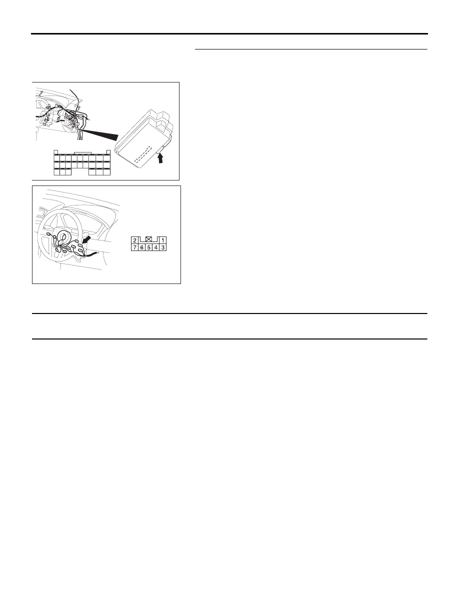
STEP 11. Check the wiring harness between key reminder 
switch connector C-310 (terminal 1) and ETACS-ECU 
connector C-218 (terminal 63).
Q: Is the wiring harness between key reminder switch 

connector C-310 (terminal 1) and ETACS-ECU connector 
C-218 (terminal 63) in good condition?
YES : 
No action is necessary and testing is complete.
NO :  The wiring harness may be damaged or the 

connector(s) may have loose, corroded or damaged 
terminals, or terminals pushed back in the connector. 
Repair the wiring harness as necessary. Verify that 
the ignition key hole illumination lamp illuminates 
normally.

INSPECTION PROCEDURE K-5: Interior Light: The interior lamp automatic shutoff function does not 
work normally.

NOTE: This troubleshooting procedure requires the 
use of diagnostic tool MB991958 and SWS monitor 
kit MB991813. For details on how to use the SWS 
monitor, refer to "How to connect SWS monitor 

P.54B-13

."

.

CIRCUIT OPERATION

The ETACS-ECU operates the interior lamp auto-
matic shutdown function according to the following 
switch signals:

• Ignition switch (ACC)

• Ignition switch (IG1)

• Front door switch (LH)

• Door switches

• interior lamp loaded signal

.

TECHNICAL DESCRIPTION (COMMENT)

If the function does not work normally, the input cir-
cuit system from the switches or the ETACS-ECU 
may be defective (refer to "CIRCUIT OPERATION").

.

TROUBLESHOOTING HINTS

• Refer to circuit diagrams GROUP-

90

• Refer to configuration diagrams GROUP-

80

• Trouble in input signal system

• The wiring harness or connectors may have 

loose, corroded, or damaged terminals, or termi-
nals pushed back in the connector

• The ETACS-ECU may be defective

54DB006A

CONNECTORS: C-218

JUNCTION BLOCK
(REAR VIEW)

C-218 (GR)

HARNESS SIDE

45

46

48 47

49

50
59

51
60

52

53
62

65

61

54
63

56

68

64

67 66

57

58

55

54DB004A

CONNECTOR: C-310

HARNESS SIDE

SYMPTOM PROCEDURES

SIMPLIFIED WIRING SYSTEM (SWS)

54B-390

DIAGNOSIS

Required Special Tools:

• MB991223: Harness Set

• MB991958: Diagnostic Tool (MUT-III Sub Assembly)

• MB991824: Vehicle Communication Interface (V.C.I.)

• MB991827: MUT-III USB Cable

• MB991910: MUT-III Main Harness A

• MB991813: SWS Monitor Kit

• MB991806: SWS Monitor Cartridge

• MB991812: SWS Monitor Harness (For Column-ECU)

• MB991822: Test Probe Harness

STEP 1. Check the interior lamps.
If the interior lamp switch is moved to the "door interlock posi-
tion", the interior lamps should illuminate when either door is 
opened.

Q: Do the interior lamp illuminate normally?

All the interior lamps illuminate normally. : Go to Step 2.
None of the interior lamps illuminate normally. : Refer to 

Inspection Procedure K-1 "The dome lamp do not 
illuminate and go out normally 

P.54B-359

."

Some of the interior lamps do not illuminate normally. : 

Refer to Inspection Procedure K-2 "The front dome 
lamp, rear dome lamp or trunk lamp do not illuminate 
or go out normally 

P.54B-366

."

STEP 2. Check the adjustment function.

Q: Has a setting other than "No auto-shutoff" been 

selected for the interior lamp automatic shutdown 
function by the adjustment function?
YES : 
Go to Step 3.
NO :  Set the interior lamp automatic shutdown function to 

another setting other than "No auto-shutoff".

SYMPTOM PROCEDURES

SIMPLIFIED WIRING SYSTEM (SWS)

54B-391

STEP 3. Use diagnostic tool MB991958 to select "ECU 
COMM Check" on the SWS monitor display. 
Check the ETACS-ECU.

CAUTION

To prevent damage to diagnostic tool MB991958, always 
turn the ignition switch to the "LOCK" (OFF) position 
before connecting or disconnecting diagnostic tool 
MB991958. Connect special tool MB991910 before con-
necting special tool MB991812. Be sure to connect special 
tool MB991806 after turning on special tool MB991824.
(1) Connect the special tool. Refer to "How to connect SWS 

monitor 

P.54B-13

."

(2) Turn the ignition switch to the "LOCK" (OFF) position.
(3) Operate diagnostic tool MB991958 according to the 

procedure below to display "ECU COMM Check."
a. Select "Interactive Diagnosis."
b. Select "System select."
c. Select "SWS."
d. Select "SWS MONITOR."
e. Select "ECU COMM Check."

(4) Diagnostic tool MB991958 should show "OK" on the "ECU 

COMM Check" menu for the "ETACS ECU" menu.

Q: Is "OK" displayed for the "ETACS ECU" menu?

YES : Go to Step4.
NO :  Refer to Inspection Procedure A-3 "Communication 

with the ETACS-ECU is not possible 

P.54B-74

."

00DB076A

MB991910

DATA LINK

CONNECTOR

MB991824

MB991827

AC302210

COLUMN SWITCH 
CONNECTOR

COLUMN SWITCH 
CONNECTOR AT 
HARNESS SIDE 

MB991812

AB

SYMPTOM PROCEDURES

SIMPLIFIED WIRING SYSTEM (SWS)

54B-392

STEP 4. Check the input signal by using "DATA LIST" 
menu of the SWS monitor.
Check the input signals from the following switches:

• Ignition switch: OFF

• Driver’s or front passenger’s door: open

(1) Operate diagnostic tool MB991958 according to the 

procedure below to display "ETACS ECU."
a. Select "Interactive Diagnosis."
b. Select "System select."
c. Select "SWS."
d. Select "SWS MONITOR."
e. Select "Data List."
f.

Select "ETACS ECU."

(2) Check that normal conditions are displayed for the items 

described in the table below.

Q: Does the diagnostic tool MB991958 display the items 

"IG SW (IG1)", "IG SW (ACC)" and "FRONT DOOR SW" 
as normal condition?
Normal conditions are displayed for all the items : 
Go to 

Step 5.

Normal condition is not displayed for "IG SW (IG1)" : 

Refer to Inspection Procedure M-2 "ETACS-ECU 
does not receive any signal from the ignition switch 
(IG1) 

P.54B-408

."

Normal condition is not displayed for "IG SW (ACC)" : 

Refer to Inspection Procedure M-1 "ETACS-ECU 
does not receive any signal from the ignition switch 
(ACC) 

P.54B-405

."

Normal condition is not displayed for "FRONT DOOR 
SW" : 
Refer to Inspection Procedure M-4 "ETACS-ECU 

does not receive any signal from the front door 
switches 

P.54B-413

."

ITEM NO.

ITEM NAME

NORMAL CONDITION

ITEM 30

IG SW (IG1)

OFF

ITEM 31

IG SW (ACC)

OFF

ITEM 32

FRONT DOOR SW

ON

00DB076A

MB991910

DATA LINK

CONNECTOR

MB991824

MB991827

AC302210

COLUMN SWITCH 
CONNECTOR

COLUMN SWITCH 
CONNECTOR AT 
HARNESS SIDE 

MB991812

AB


Content   ..  96  97  98  99   ..