Mitsubishi 380. Manual - part 82


  Index      Mitsubishi     Mitsubishi 380 - service repair manual 2005 year


Search            


Content   ..  80  81  82  83   ..


Mitsubishi 380. Manual - part 82


SYMPTOM PROCEDURES

SIMPLIFIED WIRING SYSTEM (SWS)

54B-325

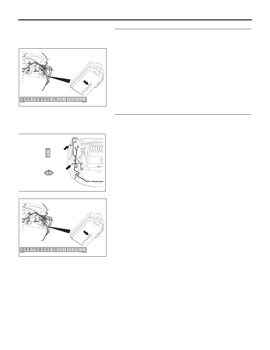
STEP 18. Check ETACS-ECU connector C-219 for loose, 
corroded or damaged terminals, or terminals pushed back 
in the connector.
Q: Is ETACS-ECU connector C-219 in good condition?

YES : Go to Step 19.
NO :  Repair or replace the damaged component(s). Refer 

to GROUP 00E, Harness Connector Inspection 

P.00E-2

. Verify that the turn-signal lamps illuminate 

normally.

STEP 19. Check the wiring harness between front 
combination lamp (RH) connector A-34 (terminal 1) and 
ETACS-ECU connector C-219 (terminal 9).

54DB014A

CONNECTOR: C-219

JUNCTION BLOCK SIDE

JUNCTION BLOCK

(REAR VIEW)

16DB444A

CONNECTOR: A-34, A-35

A-34 

A-35

54DB014A

CONNECTOR: C-219

JUNCTION BLOCK SIDE

JUNCTION BLOCK

(REAR VIEW)

SYMPTOM PROCEDURES

SIMPLIFIED WIRING SYSTEM (SWS)

54B-326

NOTE: Also check junction block connector C-214 for loose, 
corroded, or damaged terminals, or terminals pushed back in 
the connector. If junction block connector C-214 is damaged, 
repair or replace the damaged component(s) as described in 
GROUP 00E, Harness Connector Inspection 

P.00E-2

.

Q: Is the wiring harness between front combination lamp 

(RH) connector A-34 (terminal 1) and ETACS-ECU 
connector C-219 (terminal 9) in good condition?
YES : 
Replace the front combination lamp socket (RH). 

Verify that the turn-signal lamps illuminate normally.

NO :  The wiring harness may be damaged or the 

connector(s) may have loose, corroded or damaged 
terminals, or terminals pushed back in the connector. 
Repair the wiring harness as necessary. Verify that 
the turn-signal lamps illuminate normally.

STEP 20. Check side turn-signal lamp (RH) connector A-35 
for loose, corroded or damaged terminals, or terminals 
pushed back in the connector.
Q: Is side turn-signal lamp (RH) connector A-35 in good 

condition?
YES : 
Go to Step 21.
NO :  Repair or replace the damaged component(s). Refer 

to GROUP 00E, Harness Connector Inspection 

P.00E-2

. Verify that the turn-signal lamps illuminate 

normally.

STEP 21. Check the side turn-signal lamp bulb (RH).
(1) Remove the side turn-signal (RH) lamp bulb.
(2) Verify that the side turn-signal lamp bulb (RH) is not 

damaged or burned out.

Q: Is the side turn-signal (RH) lamp bulb in good 

condition?
YES : 
Go to Step 22.
NO :  Replace the side turn-signal (RH) lamp bulb. Verify 

that the turn-signal lamps illuminate normally.

54DB057A

CONNECTOR: C-214

HARNESS SIDE

10

1

6

14

5

12

13

4

11

7

2

3

8

9

16DB444A

CONNECTOR: A-34, A-35

A-34 

A-35

SYMPTOM PROCEDURES

SIMPLIFIED WIRING SYSTEM (SWS)

54B-327

STEP 22. Check the ground circuit to the side turn-signal 
lamp (RH). Measure the resistance at side turn-signal lamp 
(RH) connector A-35.
(1) Disconnect side turn-signal lamp (RH) connector A-35 and 

measure the resistance available at the wiring harness side 
of the connector.

(2) Measure the resistance value between terminal 2 and 

ground.

• The resistance should be 2 ohms or less.

Q: Is the measured resistance 2 ohms or less?

YES : Go to Step 24.
NO :  Go to Step 23.

STEP 23. Check the wiring harness between side 
turn-signal lamp (RH) connector A-35 (terminal 2) and 
ground.
Q: Is the wiring harness between side turn-signal lamp 

(RH) connector A-35 (terminal 2) and ground in good 
condition?
YES : 
Replace the side turn-signal lamp socket (RH). Verify 

that the turn-signal lamps illuminate normally.

NO :  The wiring harness may be damaged or the 

connector(s) may have loose, corroded or damaged 
terminals, or terminals pushed back in the connector. 
Repair the wiring harness as necessary. Verify that 
the turn-signal lamps illuminate normally.

16DB444A

CONNECTOR: A-34, A-35

A-34 

A-35

16DB449A

CONNECTOR A-35

(HARNESS SIDE)

16DB444A

CONNECTOR: A-34, A-35

A-34 

A-35

SYMPTOM PROCEDURES

SIMPLIFIED WIRING SYSTEM (SWS)

54B-328

STEP 24. Check ETACS-ECU connector C-219 for loose, 
corroded or damaged terminals, or terminals pushed back 
in the connector.
Q: Is ETACS-ECU connector C-219 in good condition?

YES : Go to Step 25.
NO :  Repair or replace the damaged component(s). Refer 

to GROUP 00E, Harness Connector Inspection 

P.00E-2

. Verify that the turn-signal lamps illuminate 

normally.

STEP 25. Check the wiring harness between side 
turn-signal lamp (RH) connector A-35 (terminal 1) and 
ETACS-ECU connector C-219 (terminal 9).

54DB014A

CONNECTOR: C-219

JUNCTION BLOCK SIDE

JUNCTION BLOCK

(REAR VIEW)

16DB444A

CONNECTOR: A-34, A-35

A-34 

A-35

54DB014A

CONNECTOR: C-219

JUNCTION BLOCK SIDE

JUNCTION BLOCK

(REAR VIEW)


Content   ..  80  81  82  83   ..