Mitsubishi 380. Manual - part 11


  Index      Mitsubishi     Mitsubishi 380 - service repair manual 2005 year


Search            


Content   ..  9  10  11  12   ..


Mitsubishi 380. Manual - part 11


DIAGNOSTIC TROUBLE CODE PROCEDURES

SIMPLIFIED WIRING SYSTEM (SWS)

54B-41

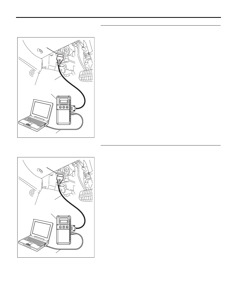
STEP 2. Using diagnostic tool MB991958, read the Engine 
ECU or A/T ECU diagnostic trouble code.
Check whether engine and automatic transaxle DTCs are set 
or not.
(1) Turn the ignition switch to the "ON" position.
(2) Check for engine and automatic transaxle DTCs.
(3) Turn the ignition switch to the "LOCK" (OFF) position.

Q: Is the DTC set?

YES : Diagnose the  Engine ECU (refer to GROUP 13A, 

Diagnosis  

P.13A-5

), or Diagnose the A/T-ECU (refer 

to GROUP 23A, Diagnosis 

P.23A-12

).

NO :  Go to Step 3.

STEP 3. Using diagnostic tool MB991958, read the for any 
diagnostic trouble code. 
Check if a DTC, which relates to CAN communication-linked 
systems below, is set.

• Combination meter

DTC indicating a time-out error related to the engine or 
automatic transaxle control system

• A/C

DTC indicating a time-out error related to the engine or 
automatic transaxle control system

(1) Turn the ignition switch to the "ON" position.
(2) Check for a DTC related to the relevant system.
(3) Turn the ignition switch to the "LOCK" (OFF) position.

Q: Is the DTC set?

YES : Go to Step 4.
NO :  Go to Step 5.

00DB076A

MB991910

DATA LINK

CONNECTOR

MB991824

MB991827

00DB076A

MB991910

DATA LINK

CONNECTOR

MB991824

MB991827

DIAGNOSTIC TROUBLE CODE PROCEDURES

SIMPLIFIED WIRING SYSTEM (SWS)

54B-42

STEP 4. Recheck for diagnostic trouble code.
Check again if the DTC is set.
(1) Turn the ignition switch to the "ON" position.
(2) Check if the DTC is set.
(3) Turn the ignition switch to the "LOCK" (OFF) position.

Q: Is the DTC set?

YES : Replace the Engine ECU. On completion, verify that 

the DTC is not reset.

NO :  A poor connection, open circuit or other intermittent 

malfunction is present in the CAN bus lines between 
the Engine-ECU and the ETACS-ECU (Refer to 
GROUP 00, How to Cope with Intermittent 
Malfunction 

P.00-14

).

STEP 5. Recheck for diagnostic trouble code.
Check again if the DTC is set.
(1) Turn the ignition switch to the "ON" position.
(2) Check if the DTC is set.
(3) Turn the ignition switch to the "LOCK" (OFF) position.

Q: Is the DTC set?

YES : Replace the ETACS-ECU. On completion, verify that 

the DTC is not reset.

NO :  A poor connection, open circuit or other intermittent 

malfunction is present in the CAN bus lines between 
the Engine ECU or A/T ECU and the ETACS-ECU 
(Refer to GROUP 00, How to Cope with Intermittent 
Malfunction 

P.00-14

).

00DB076A

MB991910

DATA LINK

CONNECTOR

MB991824

MB991827

00DB076A

MB991910

DATA LINK

CONNECTOR

MB991824

MB991827

DIAGNOSTIC TROUBLE CODE PROCEDURES

SIMPLIFIED WIRING SYSTEM (SWS)

54B-43

 DTC 013  (U1110): A/C-ECU Time-out.

CAUTION

If  DTC 013  (U1110) is set in the ETACS-ECU, 
always diagnose the CAN main bus line.

CAUTION

Whenever the ECU is replaced, ensure that the 
communication circuit is normal.

.

TROUBLE JUDGMENT

The ETACS-ECU receives air conditioning sys-
tem-related signal from the A/C-ECU. If an air condi-
tioning control system-related signal cannot be 
received,  DTC 013  (U1110) will be set.

.

TECHNICAL DESCRIPTION (COMMENT)

Current trouble

• Connector(s) or wiring harness in the CAN bus 

lines between the A/C-ECU and the 
ETACS-ECU, the power supply system to the 
A/C-ECU, the A/C-ECU, or the ETACS-ECU may 
be defective.

• Refer to circuit diagrams GROUP-

90

• Refer to configuration diagrams GROUP-

80

Past trouble

• If  DTC 013  (U1110) is stored as a past trouble, 

carry out diagnosis with particular emphasis on 
wiring and connector(s) in the CAN bus line 
between the A/C-ECU and the ETACS-ECU, and 
the power supply system to the A/C-ECU. For 
diagnosis procedures, refer to "How to cope with 
past trouble" (Refer to GROUP 00, How to treat 
past trouble 

P.00-16

).

NOTE: You cannot find a past trouble, by the 
MUT-III CAN bus diagnostics even if there is a 
failure in CAN bus lines. In this case, refer to 
GROUP 00, How to Cope with Intermittent Mal-
function 

P.00-14

 and check the CAN bus lines. 

You can narrow down the possible cause of the 
trouble by referring to the DTC, which is set 
regarding the CAN communication-linked ECUs 
(Refer to GROUP 54C, Explanation about the 
diagnostic tool (MUT-III) CAN BUS diagnostics 

P.54C-6

).

.

TROUBLESHOOTING HINTS

• The wiring harness or connectors may have 

loose, corroded, or damaged terminals, or termi-
nals pushed back in the connector

• The A/C-ECU may be defective

• The ETACS-ECU may be defective

DIAGNOSIS

Required Special Tools:

• MB991223: Harness Set

• MB991958: DIAGNOSTIC TOOL (MUT-III Sub Assembly)

• MB991824: Vehicle Communication Interface (V.C.I.)

• MB991827: MUT-III USB Cable

• MB991910: MUT-III Main Harness A

DIAGNOSTIC TROUBLE CODE PROCEDURES

SIMPLIFIED WIRING SYSTEM (SWS)

54B-44

STEP 1. Using diagnostic tool MB991958, diagnose the 
CAN bus line.

CAUTION

To prevent damage to diagnostic tool MB991958, always 
turn the ignition switch to the "LOCK" (OFF) position 
before connecting or disconnecting diagnostic tool 
MB991958.
(1) Connect diagnostic tool MB991958. Refer to "How to 

connect SWS monitor 

P.54B-13

."

(2) Turn the ignition switch to the "ON" position.
(3) Diagnose the CAN bus line.
(4) Turn the ignition switch to the "LOCK" (OFF) position.

Q: Is the CAN bus line found to be normal?

YES : Go to Step 2.
NO :  Repair the CAN bus line (Refer to GROUP 54C, 

Diagnosis 

P.54C-13

).

STEP 2. Using diagnostic tool MB991958, read the A/C 
diagnostic trouble code.
Check if an A/C-ECU DTC is set.
(1) Turn the ignition switch to the "ON" position.
(2) Check whether A/C system-related DTC is set.
(3) Turn the ignition switch to the "LOCK" (OFF) position.

Q: Is the DTC set?

YES : Diagnose the air conditioning system (Refer to 

GROUP 55, Diagnosis 

P.55-5

).

NO :  Go to Step 3.

00DB076A

MB991910

DATA LINK

CONNECTOR

MB991824

MB991827

00DB076A

MB991910

DATA LINK

CONNECTOR

MB991824

MB991827


Content   ..  9  10  11  12   ..