Mitsubishi 380. Manual - part 4


  Index      Mitsubishi     Mitsubishi 380 - service repair manual 2005 year


Search            


Content   ..  1  2  3  4  5  ..


Mitsubishi 380. Manual - part 4


SWS DIAGNOSIS

SIMPLIFIED WIRING SYSTEM (SWS)

54B-13

When the SWS communication line is monitored, 
you can determine whether the problem lies in the 
input or output signal circuit system by checking 
whether communication data is correct:

• If the switch condition does not meet the service 

data display, the input signal is defective.

• If the switch condition meets the service data dis-

play, the output signal system is defective.

• Refer to circuit diagrams GROUP-

90

• Refer to configuration diagrams GROUP-

80

NOTE:  In addition to the function-specific diag-
nostic menu, a service data menu is available for 
SWS monitor service data to check all items for 
each ECU.

6. Check the input signal circuit system

Check the relevant switch, sensor, input 
signal-side ECU and their wiring harness and 
connector.

7. Check the output signal circuit system

Check an output signal-side ECU, electrical load 
components and their wiring harness and 
connector.

HOW TO CONNECT SWS MONITOR

M1549014800706

Required Special Tools:

•  MB991958: DIAGNOSTIC TOOL (MUT-III Sub Assembly)

• MB991824: Vehicle Communication Interface (V.C.I.)

• MB991827: MUT-III USB Cable

• MB991910: MUT-III Main Harness A

• MB991813: SWS Monitor Kit

• MB991806: SWS Monitor Cartridge

• MB991812: SWS Monitor Harness (For Column-ECU)

• MB991822: Probe Harness

CAUTION

To prevent damage to diagnostic tool MB991958, always 
turn the ignition switch to the "LOCK" (OFF) position 
before connecting or disconnecting diagnostic tool 
MB991958. Connect the main harness A MB991910 before 
connecting the SWS monitor harness (for column-ECU) 
MB991812. Be sure to connect SWS monitor cartridge 
MB991806 after turning on the V.C.I. MB991924.
1. Ensure that the ignition switch is at the "LOCK" (OFF) 

position.

2. Start up the personal computer.

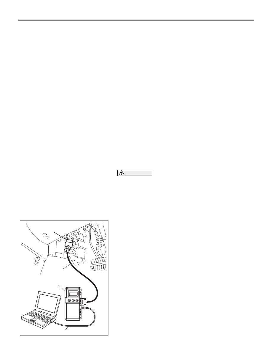
3. Connect special tool MB991827 to special tool MB991824 

and the personal computer.

4. Connect special tool MB991910 to special tool MB991824.

5. Connect special tool MB991910 to the data link connector.

00DB076A

MB991910

DATA LINK

CONNECTOR

MB991824

MB991827

SWS DIAGNOSIS

SIMPLIFIED WIRING SYSTEM (SWS)

54B-14

6. Remove the steering column cover.

7. Remove the steering column switch connector.

8. Connect special tool MB991812 to the column switch 

connector.

9. Connect special tool MB991812 to special tool MB991806.

10.Connect special tool MB991806 to special tool MB991824.

11.Turn the power switch of special tool MB991824 to the "ON" 

position.

NOTE: When special tool MB991824 is energised, special 
tool MB991824 indicator lamp will be illuminated in a green 
color.

12.Start the MUT-III system on the personal computer.

AC302210

COLUMN SWITCH 
CONNECTOR

COLUMN SWITCH 
CONNECTOR AT 
HARNESS SIDE 

MB991812

AB

AC208681

MB991806

AB

MB991812

MB991824

MB991910

MB991827

SWS DIAGNOSIS

SIMPLIFIED WIRING SYSTEM (SWS)

54B-15

HOW TO CHECK ECUS

M1549014900640

1. Use the diagnostic tool MB991958 (MUT-III Sub 

Assembly) and the SWS monitor kit to check 
ECUs.

2. The following ECUs can be checked by using the 

diagnostic tool MB991958 (MUT-III Sub 
Assembly) and the SWS monitor kit.

NOTE:  The "ECU COMM Check" function checks 
the communication status of ECUs. "NG" does not 
always mean ECU malfunction. If a malfunction is 
found by the "ECU COMM Check", proceed to 
"Symptom Procedure" (Refer to 

P.54B-57

).

SWS monitor kit-compatible ECUs and their conditions

NOTE: 

.

• *

1

: If the ignition switch is turned to "LOCK" (OFF) 

or "ACC" when "NG" is displayed beside "ETACS 
ECU" or the signal request line is abnormal, the 
diagnostic tool shows "NG" beside the "COLUMN 
ECU".

• *

2

: When "NG" is displayed beside "ETACS 

ECU", the diagnostic tool shows "NG" beside the 
"FRONT ECU" and "SUNROOF ECU".

SERVICE DATA CHECK

M1549015000714

Use the diagnostic tool MB991958 (MUT-III Sub 

Assembly) and the SWS monitor kit to check 
"Data List" or "Function Diag.". This "Data List" or 
"Function Diag." check is applicable for signals, 
which are transmitted and received through the 
SWS communication line. For input signals, which 
are not compatible with the SWS monitor kit, refer 
to the Pulse Check procedure (by using the 
diagnostic tool or voltmeter) 

P.54B-24

.

1. The following input signals can be checked by 

using the diagnostic tool MB991958 (MUT-III Sub 
Assembly) and the SWS monitor kit.

NOTE:  If a problem is found in the "Service Data" 
check, refer to Input Signal Chart 

P.54B-61

.

<DATA LIST REFERENCE TABLE>

The table below shows the service data and their 
normal condition, which are displayed during the 
"Data List."

.

ITEM 
No.

ECUS TO BE 
CHECKED

DISPLAY ON 
DIAGNOSTIC 
TOOL

NORMAL 
CONDITI
ON

ECU CONDITION

80

Column switch 
(column-ECU)

COLUMN ECU

OK*

1

All of the column switch, power supply, 
ground and interconnecting 
communication lines are normal

83

ETACS-ECU

ETACS-ECU

OK

All of the ETACS-ECU switch, power 
supply, ground and interconnecting 
communication lines are normal

84

Front-ECU

FRONT ECU

OK*

2

All of the front-ECU, power supply, ground 
and interconnecting communication lines 
are normal

86

Sunroof motor 
assembly 
(sunroof-ECU)

SUNROOF ECU

OK*

2

All of the sunroof motor assembly, power 
supply, ground and interconnecting 
communication lines are normal

SWS DIAGNOSIS

SIMPLIFIED WIRING SYSTEM (SWS)

54B-16

COLUMN ECU

.

CHECK 
ITEM

ITEM NO. DISPLAY ON 

DIAGNOSTIC 
TOOL

CHECK CONDITION

NORMAL 
CONDITION

Dimmer 
switch

02

DIMMER SW

Dimmer switch: ON

ON

Dimmer switch: OFF

OFF

Windshield 
washer 
switch

09

FRONT 
WASH.SW

Windshield washer switch: ON

ON

Windshield washer switch: OFF

OFF

Headlamp 
switch

00

HEADLAMP 
SW

Lighting switch: HEAD

ON

Lighting switch: Other than HEAD

OFF

Windshield 
high-speed 
wiper switch

07

HI WIPER SW

Wiper switch: HI

ON

Wiper switch: Other than HI

OFF

With or 
without 
windshield 
intermittent 
wiper interval 
adjusting 
knob

15

INT WIPE 
KNOB

Vehicles with intermittent wiper control

EQUIP

Vehicles without intermittent wiper control

NON

Windshield 
intermittent 
wiper switch

05

INT WIPER SW Wiper switch: INT

ON

Wiper switch: Other than INT

OFF

Windshield 
low-speed 
wiper switch

06

LO WIPER SW Wiper switch: LO

ON

Wiper switch: Other than LO

OFF

Windshield 
mist wiper 
switch

08

MIST WIPER 
SW

Wiper switch: Mist

ON

Wiper switch: Other than "Mist" position

OFF

Passing lamp 
switch

03

PASSING SW

Passing lamp switch: ON

ON

Passing lamp switch: OFF

OFF

Tail lamp 
switch

01

TAILLAMP SW Lighting switch: TAIL

ON

Lighting switch: OFF

OFF

Turn-signal 
lamp switch 
(LH)

11

T/S LH SW

Turn-signal lamp switch: LH

ON

Turn-signal lamp switch: Other than LH

OFF

Turn-signal 
lamp switch 
(RH)

10

T/S RH SW

Turn-signal lamp switch: RH

ON

Turn-signal lamp switch: Other than RH

OFF


Content   ..  1  2  3  4  5  ..