Mitsubishi Grandis. Manual - part 791
AUTO-CRUISE CONTROL
ENGINE AND EMISSION CONTROL
17-5
SPECIAL TOOL
M1172000600361
TROUBLESHOOTING
DIAGNOSIS TROUBLESHOOTING FLOW
M1172002000332
Refer to GROUP 00 - How to Use
Troubleshooting/Inspection Service Points
DIAGNOSIS FUNCTION
M1172002100340
METHOD OF READING THE DIAGNOSIS
CODE
Use the MUT-III to read the diagnosis code (Refer to
GROUP 00
− How to Use
Troubleshooting/Inspection Service Points
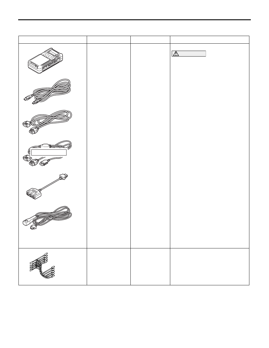
Tool
Number
Name
Use
MB991955
A: MB991824
B: MB991827
C: MB991910
D: MB991911
E: MB991825
F: MB991826
MUT-III
sub-assembly
A: Vehicle
Communicati
on Interface
(V. C. I.)
B: MUT-III USB
cable
C: MUT-III main
harness A
(Vehicles with
CAN
communicatio
n system)
D: MUT-III main
harness B
(Vehicles
without CAN
communicatio
n system)
E: MUT-III
measurement
adapter
F: MUT-III
trigger
harness
Reading diagnosis code
CAUTION
MUT-III main harness A should
be used. MUT-III main harness B
should not be used for this
vehicle. If you connect MUT-III
main harness B instead, the CAN
communication does not
function correctly.
MB991658
Test harness
Inspection of data list
MB991910
MB991826
MB991955
MB991911
MB991824
MB991827
MB991825
A
B
C
D
E
F
DO NOT USED
MB991658