Mitsubishi Grandis. Manual - part 784
ON-VEHICLE SERVICE
MULTIPORT FUEL INJECTION (MPI)
13A-387
(3) Remove the rear scuff plate (Refer to GROUP
52A, Trim Removal and Installation
and turn up the floor mat.
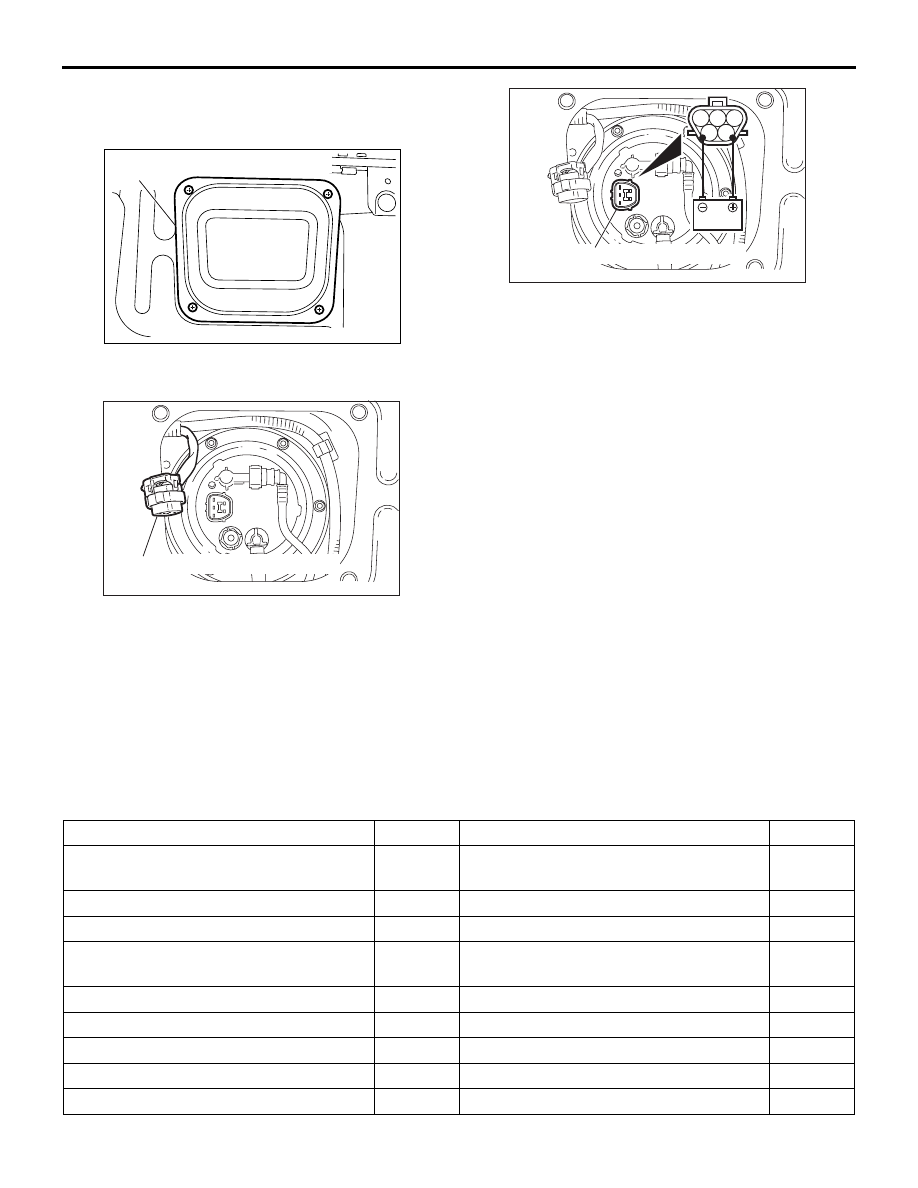
(4) Remove the rear floor fuel gauge maintenance
hole cover (LH).
(5) Disconnect the fuel tank pump and gauge
assembly connector.
(6) When the fuel pump drive connector (Fuel
tank pump and gauge assembly side) is
attached directly to the battery, check if the
sound of the fuel pump operation can be
heard. If no operating sound is heard, replace
the fuel tank pump (Refer to GROUP 13B,
Fuel Pump Module Disassembly and
Assembly
NOTE: As the fuel pump is an in-tank type, the
fuel pump sound is hard to hear. Then check
the sound from the tank inlet.
(7) Connect fuel tank pump and gauge assembly
connector.
(8) Install the rear floor fuel gauge maintenance
hole cover (LH).
(9) Return the floor mat and install the rear scuff
plate. (Refer to GROUP 52A, Trim Removal
and Installation
(10)Install the rail cover outer, the rail cover inner
and the second seat assembly. (Refer to
GROUP 52A, Second Seat Assembly
Removal and Installation
).
4. Install the fuel tank cap.
COMPONENT LOCATION
M1131002101078
AC301330
AD
Rear floor fuel gauge maintenance
hole cover
AC301293AC
Fuel tank pump and gauge assembly
connector
AC301523
1
2
3
4
5
Fuel tank pump and gauge assembly
connector
AC
Name
Symbol
Name
Symbol
Accelerator pedal position sensor
U
Engine-ECU <M/T> or engine-A/T-ECU
<A/T> (with barometric pressure sensor)
X
A/C relay
K
Engine control relay
K
A/C switch
T
Engine coolant temperature sensor
G
Air flow sensor
(with intake air temperature sensor)
I
Engine warning lamp
(check engine lamp)
S
Camshaft position sensor
G
Fuel pump relay (1) and (2)
V
Crank angle sensor
L
Ignition coil
O
Cylinder 1,4 oxygen sensor (front)
M
Inhibitor switch <A/T>
R
Cylinder 1,4 oxygen sensor (rear)
N
Injector
D
Cylinder 2,3 oxygen sensor (front)
Q
Oil control valve
G