Mitsubishi Grandis. Manual - part 613


  Index      Mitsubishi     Mitsubishi Grandis - service repair manual


Search            


Content   ..  611  612  613  614   ..


Mitsubishi Grandis. Manual - part 613


DIAGNOSIS

CONTROLLER AREA NETWORK (CAN)

54D-550

connector (CAN2) terminal No.11

OK: 2 

 or less

(5) Continuity between C-125 intermediate 

connector terminal No.27 and C-09 joint 
connector (CAN2) terminal No.22

OK: 2 

 or less

CAUTION

Strictly observe the specified wiring harness 
repair procedure. For details refer to 

P.54D-8

.

Q: Are the check results normal?

YES : 

<All the voltages measure 2 

Ω or less> Go 

to Step 37      .

NO : 

<Either or all of the resistances measure 
more than 2 

Ω> Repair the wiring harness 

between joint connector (CAN2) and the 
intermediate connector.

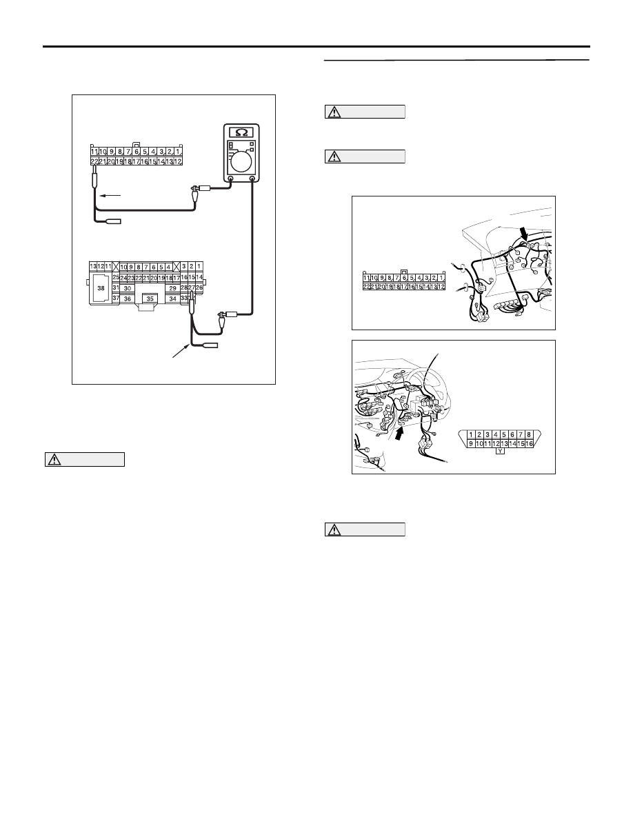
STEP 37. Resistance measurement at C-09 joint 
connector (CAN2) and C-126 diagnosis 
connector.

CAUTION

A digital multimeter should be used. For details 
refer to 

P.54D-8

.

CAUTION

The test wiring harness should be used. For 
details refer to 

P.54D-8

.

(1) Disconnect the connector, and measure at the 

wiring harness side.

(2) Ignition switch: OFF (LOCK)

CAUTION

When measuring the resistance, disconnect the 
negative battery terminal. For details refer to 

P.54D-8

.

(3) Ensure that the negative battery terminal is 

AC312553

AC312553 AP

Harness side: C-09

Test
harness

Female side: C-125

Test harness

AC310628AY

Connector: C-09 <RHD>

C-09 (GR)

Harness side

AC310631AK

Connector: C-126 <RHD>

C-126 (B)

Harness side 
(Front side)

DIAGNOSIS

CONTROLLER AREA NETWORK (CAN)

54D-551

disconnected.

(4) Continuity between C-09 joint connector (CAN2) 

terminal No.7 and C-126 diagnosis connector 

terminal No.6

OK: 2 

 or less

(5) Continuity between C-09 joint connector (CAN2) 

terminal No.18 and C-126 diagnosis connector 
terminal No.14

OK: 2 

 or less

CAUTION

Strictly observe the specified wiring harness 
repair procedure. For details refer to 

P.54D-8

.

Q: Are the check results normal?

YES : 

<All the resistances measure 2 

Ω or less> 

Diagnostics item 12: Diagnose shorts 
between CAN_L and H lines. Refer to 

P.54D-378

.

NO : 

<Either or all of the resistances measure 
more than 2 

Ω> Repair the wiring harness 

between joint connector (CAN1) and the 
diagnosis connector.

AC312553

Harness side: C-09

Test
harness

AX

Front side : C-126

Test
harness

AC312553 AZ

Front side : C-126

Test
harness

Test
harness

Harness side: C-09

DIAGNOSIS

CONTROLLER AREA NETWORK (CAN)

54D-552

Diagnostic Item 21: Diagnose the lines between the joint connectors (CAN1 and CAN2) <LH drive 
vehicles>

CAUTION

When servicing a CAN bus line, earth yourself by 
touching a metal object such as an unpainted 
water pipe. If you fail to do, a component 
connected to the CAN bus line may be broken.

TROUBLE JUDGMENT

If the MUT-III cannot receive any signal from the 
ABS-ECU and the engine-ECU <M/T> or 
engine-A/T-ECU <A/T>, CAN bus line connector(s) 
are broken or an open circuit has occurred.

COMMENTS ON TROUBLE SYMPTOM

The CAN bus line wire or connectors may have 
loose, corroded, or damage terminals, or terminals 
pushed back in the connector.

ENGINE-ECU<M/T>
ENGINE·A/T-ECU<A/T>

COMBINATION
METER

Wire colour code
B : Black     LG : Light green     G : Green     L : Blue     W : White     Y : Yellow     SB : Sky blue
BR : Brown     O : Orange     GR : Gray     R : Red     P : Pink     V : Violet

DIAGNOSIS

CONTROLLER AREA NETWORK (CAN)

54D-553

POSSIBLE CAUSES

• Damaged harness wires and connectors

DIAGNOSTIC PROCEDURE

STEP 1. Connector check: C-09 joint connector 
(CAN2) and C-125 intermediate connector

CAUTION

The strand end of the twist wire should be within 
10 cm from the connector. For details refer to 

P.54D-8

.

When checking the joint connector, ensure that its 
wiring harness side is not damaged.

Q: Are the check results normal?

YES : 

Go to Step 2 .

NO : 

Repair a defective connector or replace the 
joint connector.

STEP 2. Resistance measurement at C-09 joint 
connector (CAN2) and C-125 intermediate 
connector.

CAUTION

A digital multimeter should be used. For details 
refer to 

P.54D-8

.

CAUTION

The test wiring harness should be used. For 
details refer to 

P.54D-8

.

(1) Disconnect the joint connector (CAN2) and the 

intermediate connector, and measure at the 
wiring harness side.

(2) Ignition switch: OFF (LOCK)

CAUTION

When measuring the resistance, disconnect the 
negative battery terminal. For details refer to 

P.54D-8

.

(3) Ensure that the negative battery terminal is 

AC310615

AU

Harness side

Connector: C-09 <LHD>

C-09 (GR)

AC310613

AD

Connector: C-125 <LHD>

AC209350

1

12

2

13

3

14

4

15

5

16

6

17

7

18

8

19

9

20

10

21

11

22

AC

Short pin

AC310615

AU

Harness side

Connector: C-09 <LHD>

C-09 (GR)

AC310613

AD

Connector: C-125 <LHD>


Content   ..  611  612  613  614   ..