Mitsubishi Grandis. Manual - part 553
DIAGNOSIS
CONTROLLER AREA NETWORK (CAN)
54D-310
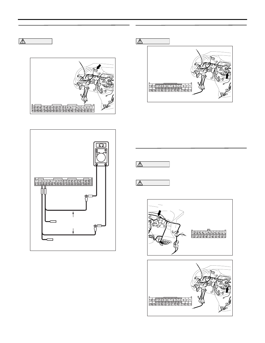
STEP 7. Resistance measurement at C-02
combination meter connector.
CAUTION
A digital multimeter should be used. For details
refer to
(1) Remove the combination meter, and measure at
the equipment side.
(2) Resistance between C-02 combination meter
connector terminal Nos. 23 and 24
OK: 120
± 20 Ω
Q: Is the check result normal?
YES :
<Within 120
± 20 Ω> Follow diagnostic item
17, Diagnose CAN bus lines thoroughly.
Refer to
NO :
<Not within 120
± 20 Ω> Replace the
combination meter.
STEP 8. Connector check: C-106 A/C-ECU
connector
CAUTION
The strand end of the twist wire should be within
10 cm from the connector. For details refer to
Q: Is the check result normal?
YES :
Go to Step 9.
NO :
Repair the defective connector.
STEP 9. Resistance measurement at C-09 joint
connector (CAN2).
CAUTION
A digital multimeter should be used. For details
refer to
.
CAUTION
The test wiring harness should be used. For
details refer to
(1) Disconnect the joint connector (CAN2) and the
A/C-ECU connector, and measure at the wiring
AC310613
BB
Connector: C-02 <LHD>
Harness side
AC204740
AC204740
AC204740
AC204740DS
Equipment side: C-02
Test
harness
AC310613
AB
Connector: C-106 <LHD>
Harness side
AC310615
AU
Harness side
Connector: C-09 <LHD>
C-09 (GR)
AC310613
AB
Connector: C-106 <LHD>
Harness side