Mitsubishi Grandis. Manual - part 546


  Index      Mitsubishi     Mitsubishi Grandis - service repair manual


Search            


Content   ..  544  545  546  547   ..


Mitsubishi Grandis. Manual - part 546


DIAGNOSIS

CONTROLLER AREA NETWORK (CAN)

54D-282

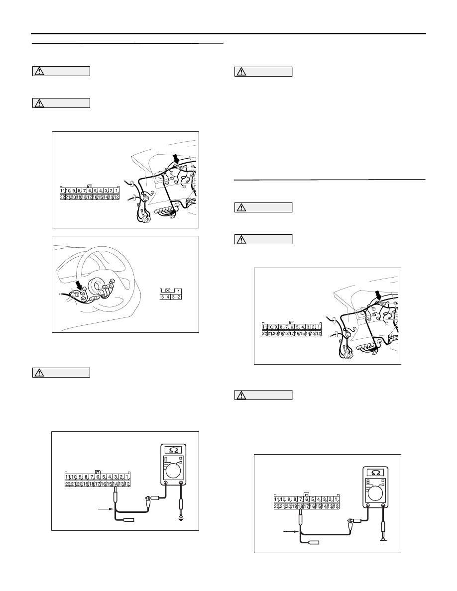
STEP 19. Resistance measurement at C-09 joint 
connector (CAN2).

CAUTION

A digital multimeter should be used. For details 
refer to 

P.54D-8

.

CAUTION

The test wiring harness should be used. For 
details refer to 

P.54D-8

.

(1) Disconnect the joint connector (CAN2) and the 

steering wheel angle sensor connector, and 
measure at the wiring harness side.

CAUTION

When measuring the resistance, disconnect the 
negative battery terminal. For details refer to 

P.54D-8

.

(2) Ensure that the negative battery terminal is 

disconnected.

(3) Resistance between C-09 joint connector (CAN2) 

terminal No.14 and body earth

OK: 1 k

 or more

CAUTION

Strictly observe the specified wiring harness 
repair procedure. For details refer to 

P.54D-8

.

Q: Is the check result normal?

YES : 

<1 k

Ω or more> Follow diagnostic item 20, 

Diagnose CAN bus lines thoroughly. Refer 
to 

P.54D-526

.

NO : 

<less than 1 k

Ω> Repair the wiring harness 

between the joint connector (CAN2) and the 
steering angle sensor connector.

STEP 20. Resistance measurement at C-09 joint 
connector (CAN2).

CAUTION

A digital multimeter should be used. For details 
refer to 

P.54D-8

.

CAUTION

The test wiring harness should be used. For 
details refer to 

P.54D-8

.

(1) Disconnect the connector, and measure at the 

wiring harness side.

CAUTION

When measuring the resistance, disconnect the 
negative battery terminal. For details refer to 

P.54D-8

.

(2) Ensure that the negative battery terminal is 

disconnected.

(3) Resistance between C-09 joint connector (CAN2) 

AC310628AY

Connector: C-09 <RHD>

C-09 (GR)

Harness side

AC310183

AF

Connector: C-306 <RHD>

Harness side

AC209364ML

Harness side: C-09

Test
harness

AC310628AY

Connector: C-09 <RHD>

C-09 (GR)

Harness side

AC209364LG

Harness side: C-09

Test
harness

DIAGNOSIS

CONTROLLER AREA NETWORK (CAN)

54D-283

terminal No.18 and body earth

OK: 1 k

 or more

CAUTION

Strictly observe the specified wiring harness 
repair procedure. For details refer to 

P.54D-8

.

Q: Is the check result normal?

YES : 

<1 k

Ω or more> Follow diagnostic item 20, 

Diagnose CAN bus lines thoroughly. Refer 
to 

P.54D-526

.

NO : 

<less than 1 k

Ω> Repair the wiring harness 

between the joint connector (CAN2) and the 
diagnosis connector.

STEP 21. Resistance measurement at C-09 joint 
connector (CAN2).

CAUTION

A digital multimeter should be used. For details 
refer to 

P.54D-8

.

CAUTION

The test wiring harness should be used. For 
details refer to 

P.54D-8

.

(1) Disconnect the connector, and measure at the 

wiring harness side.

CAUTION

When measuring the resistance, disconnect the 
negative battery terminal. For details refer to 

P.54D-8

.

(2) Ensure that the negative battery terminal is 

disconnected.

(3) Resistance between C-09 joint connector (CAN2) 

terminal No.22 and body earth

OK: 1 k

 or more

CAUTION

Strictly observe the specified wiring harness 
repair procedure. For details refer to 

P.54D-8

.

Q: Is the check result normal?

YES : 

<1 k

Ω or more> Follow diagnostic item 20, 

Diagnose CAN bus lines thoroughly. Refer 
to 

P.54D-526

.

NO : 

<less than 1 k

Ω> Repair the wiring harness 

between the joint connector (CAN2) and the 
intermediate connector.

STEP 22. Connector check: A-07 joint connector 
(CAN1)
NOTE: When checking A-07 joint connector (CAN1), 
disassemble and check the engine compartment 
relay box by referring to 

P.54D-616

.

CAUTION

The strand end of the twist wire should be within 
10 cm from the connector. For details refer to 

P.54D-8

.

When checking the joint connector, ensure that its 
wiring harness side is not damaged.

Q: Is the check result normal?

YES : 

Go to Step 23.

NO : 

Repair a defective connector or replace the 
joint connector (front wiring harness 
assembly).

AC310628AY

Connector: C-09 <RHD>

C-09 (GR)

Harness side

AC209364MH

Harness side: C-09

Test harness

AC302572AD

Connector: A-07

Harness side

DIAGNOSIS

CONTROLLER AREA NETWORK (CAN)

54D-284

STEP 23. Resistance measurement at the A-07 
joint connector (CAN1).
NOTE: When checking A-07 joint connector (CAN1), 
disassemble and check the engine compartment 
relay box by referring to 

P.54D-616

.

CAUTION

A digital multimeter should be used. For details 
refer to 

P.54D-8

.

CAUTION

The test wiring harness should be used. For 
details refer to 

P.54D-8

.

(1) Disconnect the connector, and measure at the 

wiring harness side.

CAUTION

When measuring the resistance, disconnect the 
negative battery terminal. For details refer to 

P.54D-8

.

(2) Ensure that the negative battery terminal is 

disconnected.

(3) Resistance between A-07 joint connector (CAN1) 

terminal No.3 and body earth

OK: 1 k

 or more

(4) Resistance between A-07 joint connector (CAN1) 

terminal No.2 and body earth

OK: 1 k

 or more

Q: Are the check result normal?

YES <all of the measurement results show 1 k

 or 

more> : 

Go to Step 29.

NO <The resistance between terminal No.3 and 
body earth is less than 1 k

> : 

Go to Step 24.

NO <The resistance between terminal No.2 and 
body earth is less than 1 k

> : 

Go to Step 27.

STEP 24. Connector check: A-16 intermediate 
connector

CAUTION

The strand end of the twist wire should be within 
10 cm from the connector. For details refer to 

P.54D-8

.

Q: Is the check result normal?

YES : 

Go to Step 25.

NO : 

Repair the defective connector.

AC302572AD

Connector: A-07

Harness side

AC209364

Harness side: A-07

AC209364LN

Test
harness

AC209364

Harness side: A-07

AC209364LO

Test
harness

AC310398

AC

Connector: A-16 <RHD>

A-16 (B)

DIAGNOSIS

CONTROLLER AREA NETWORK (CAN)

54D-285

STEP 25. Resistance measurement at the A-07 
joint connector (CAN1).
NOTE: When checking A-07 joint connector (CAN1), 
disassemble and check the engine compartment 
relay box by referring to 

P.54D-616

.

CAUTION

A digital multimeter should be used. For details 
refer to 

P.54D-8

.

CAUTION

The test wiring harness should be used. For 
details refer to 

P.54D-8

.

(1) Disconnect the joint connector (CAN1) and the 

intermediate connector, and measure at the 
wiring harness side.

CAUTION

When measuring the resistance, disconnect the 
negative battery terminal. For details refer to 

P.54D-8

.

(2) Ensure that the negative battery terminal is 

disconnected.

(3) Resistance between A-07 joint connector (CAN1) 

terminal No.3 and body earth

OK: 1 k

 or more

Q: Is the check result normal?

YES : 

<1 k

Ω or more> Go to Step 26.

NO : 

<less than 1 k

Ω> Repair the wiring harness 

between the joint connector (CAN1) and the 
intermediate connector.

STEP 26. Resistance measurement at the A-16 
intermediate connector.

CAUTION

A digital multimeter should be used. For details 
refer to 

P.54D-8

.

CAUTION

The test wiring harness should be used. For 
details refer to 

P.54D-8

.

(1) Disconnect the engine-ECU <M/T> or 

engine-A/T-ECU <A/T> connector and the 

AC302572AD

Connector: A-07

Harness side

AC310398

AC

Connector: A-16 <RHD>

A-16 (B)

AC209364

Harness side: A-07

AC209364LN

Test
harness

AC310398

AC

Connector: A-16 <RHD>

A-16 (B)

AC310628AW

Harness side

Connector: C-112 <RHD>

C-112 (GR)

61

62

63

64

65

66

67

68

69

70

71

72

73

74

75

76

77

78

79

80

81

82

83

84

85

86

87

88

89


Content   ..  544  545  546  547   ..