Mitsubishi Grandis. Manual - part 497
DIAGNOSIS
CONTROLLER AREA NETWORK (CAN)
54D-86
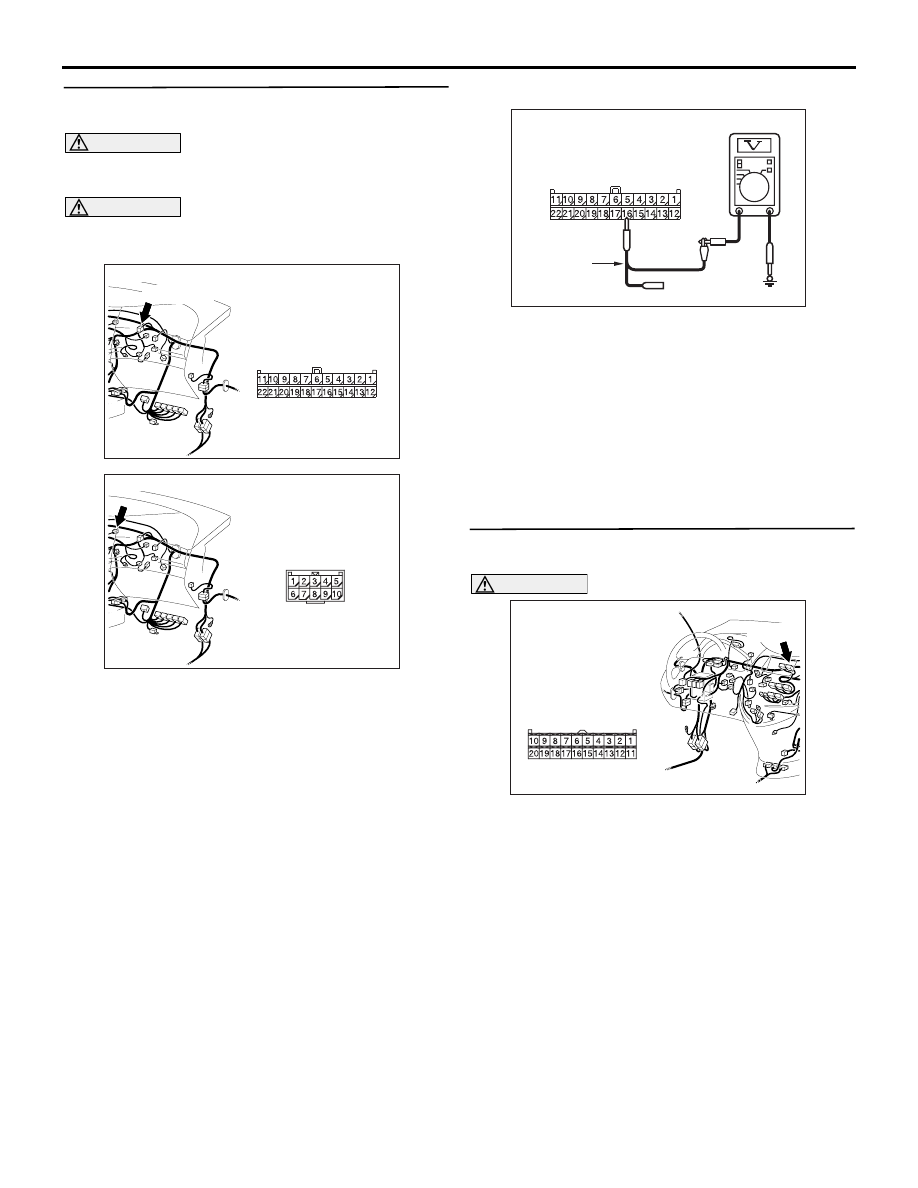
STEP 13. Voltage measurement at the C-09 joint
connector (CAN2).
CAUTION
A digital multimeter should be used. For details
refer to
CAUTION
The test wiring harness should be used. For
details refer to
(1) Disconnect the joint connector (CAN2) and the
jumper connector, and measure at the wiring
harness side.
(2) Connect the negative battery terminal, and turn
the ignition switch to the ON position.
(3) Voltage between C-09 joint connector (CAN2)
terminal No.16 and body earth
OK: Less than 1.0 V
(4) Disconnect the negative battery terminal.
Q: Is the check result normal?
YES :
<1.0 V or less> Go to Step 14.
NO :
<more than 1.0 V> Repair the wiring
harness between the joint connector
(CAN2) and the jumper connector.
STEP 14. Connector check: C-07 centre display
connector
CAUTION
The strand end of the twist wire should be within
10 cm from the connector. For details refer to
Q: Is the check result normal?
YES :
Go to Step 15 .
NO :
Repair the defective connector.
AC310615
AU
Harness side
Connector: C-09 <LHD>
C-09 (GR)
AC310615
AV
Connector: C-37 <LHD>
AC209365JT
Harness side: C-09
Test
harness
AC310613
BC
Connector: C-07 <LHD>
Harness side
C-07 (B)