Mitsubishi Grandis. Manual - part 488
DIAGNOSIS
CONTROLLER AREA NETWORK (CAN)
54D-50
the ignition switch to the ON position.
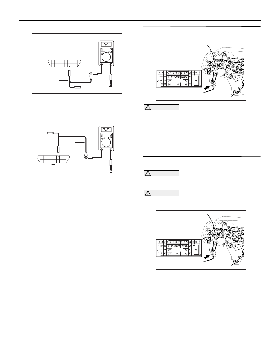
(3) Voltage between C-126 diagnosis connector
terminal No.14 and body earth
OK: 4.0 V or less
(4) Voltage between C-126 diagnosis connector
terminal No.6 and body earth
OK: 4.0 V or less
(5) Disconnect the negative battery terminal.
Q: Is the check result normal?
YES <all of the measurement results show 4.0 V or
less> :
Follow diagnostic Item 17, Diagnose CAN
bus lines thoroughly. Refer to
NO <The voltage between terminal No.14 and body
earth is more than 4.0 V> :
Go to Step 3 .
NO <The voltage between terminal No.6 and body
earth is more than 4.0 V> :
Go to Step 28 .
STEP 3. Connector check: C-125 intermediate
connector
CAUTION
The strand end of the twist wire should be within
10 cm from the connector. For details refer to
Q: Is the check result normal?
YES :
Go to Step 4 .
NO :
Repair the defective connector.
STEP 4. Voltage measurement at the C-125
intermediate connector.
CAUTION
A digital multimeter should be used. For details
refer to
.
CAUTION
The test wiring harness should be used. For
details refer to
(1) Disconnect the connector, and measure at its
male-side intermediate connector (at the front
wiring harness side).
(2) Connect the negative battery terminal, and turn
AC209365JP
8
16
15
7
5
13 14
6
12
4
2
10 11
3
9
1
Harness side: C-126
(Front side)
Test
Harness
AC209365
Harness side: C-126
(Front side)
Test
harness
JO
Y
8
16
15
7
5
1314
6
12
4
2
1011
3
9
1
AC310613
AD
Connector: C-125 <LHD>
AC310613
AD
Connector: C-125 <LHD>