Mitsubishi Grandis. Manual - part 485
DIAGNOSIS
CONTROLLER AREA NETWORK (CAN)
54D-38
NOTE: If the diagnostic items other than No.19
cannot resolve the trouble, follow diagnostic item 19,
Diagnose CAN bus lines thoroughly.
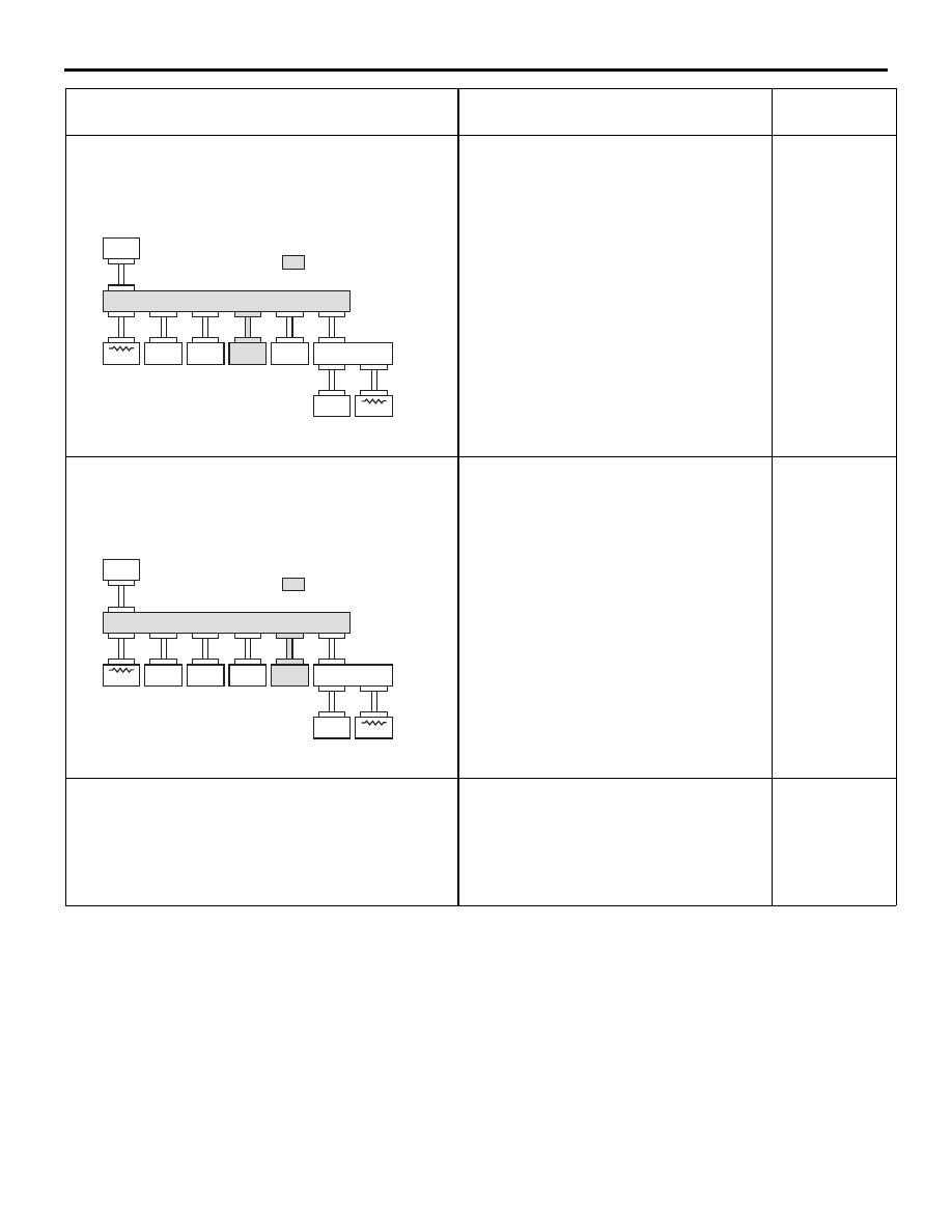
<Comment>
Harness disconnection or loose connection in red
displayed area is
estimated.
Diagnostic Item 33
Diagnose the lines from the main bus
line to the A/C-ECU <RH drive vehicles>
<Comment>
Harness disconnection or loose connection in red
displayed area is
estimated.
Diagnostic Item 35
Diagnose the lines from the main bus
line to the SRS-ECU <RH drive
vehicles>
If the screen other than above is shown
Troubles are present at two or more
spots. Diagnose CAN bus lines by
referring to the trouble spot pinpoint
procedures. If the trouble still can not be
resolved, refer to diagnostic item 19,
Diagnose CAN bus lines thoroughly.
−
MUT-III SCREEN
DIAGNOSIS DETAILS
REFERENCE
PAGE
AC309837
: Red section
on screen
MUT
J/C (2)
METER
ETACS
J/C (1)
ABS-ECU
ENG/AT-ECU
C. DISPLAY
SRS-ECU
A/C-ECU
AO
AC309837
: Red section
on screen
MUT
J/C (2)
METER
ETACS
J/C (1)
ABS-ECU
ENG/AT-ECU
C. DISPLAY
SRS-ECU
A/C-ECU
AN