Mitsubishi Grandis. Manual - part 67
SYMPTOM PROCEDURES
SMART WIRING SYSTEM (SWS) NOT USING SWS MONITOR
54B-265
Inspection Procedure J-4: Vehicle speed-dependent unfolding function does not work normally.
CAUTION
Whenever the ECU is replaced, ensure that the
input and output signal circuits are normal.
COMMENTS ON TROUBLE SYMPTOM
The ETACS-ECU operates this function in
accordance with the input signals below.
• Ignition switch (IG1)
• Vehicle speed signal
If this function does not work normally, these input
signal circuit(s) or the ETACS-ECU may be
defective. In addition, it is possible that the function
except the vehicle speed-dependent unfolding
function has been set by using the customized
function.
POSSIBLE CAUSES
• The CAN bus line is defective.
• Malfunction of ETACS-ECU
• Damaged harness wires and connectors
DIAGNOSTIC PROCEDURE
Step 1. Pulse check
Check the input signals below which are related to
the electric retractable remote controlled door mirror
vehicle speed-dependent unfolding function.
OK: The MUT-III sounds or the voltmeter
needle fluctuates.
Q: Is the check result normal?
All the signals are received normally. :
Go to Step
The ignition switch (IG1) signal is not received. :
Refer to inspection procedure Q-2 "The
ignition switch (IG1) signal is not received
The vehicle speed signal is not received. :
Refer to
inspection procedure Q-25 "The vehicle
speed signal is not received
."
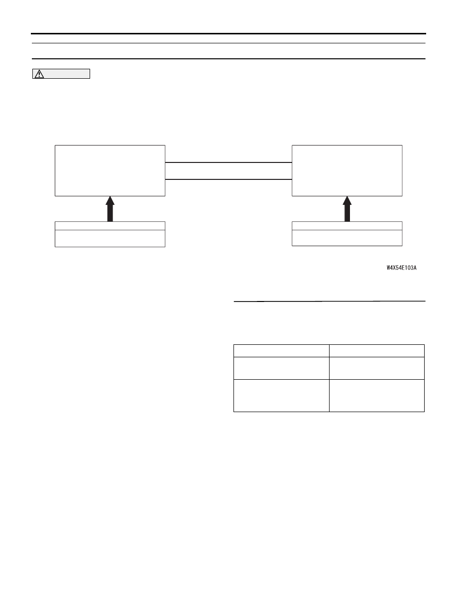
SPEED SIGNAL
COMBINATION METER
CAN COMMUNICATION LINE
(CAN_L LINE)
CAN COMMUNICATION LINE
(CAN_H LINE)
INPUT SIGNAL
ETACS-ECU
INPUT SIGNAL
IGNITION SWITCH (IG1)
Vehicle Speed-Dependent Unfolding Function
System switch
Check condition
Ignition switch (IG1)
When turned from ACC
to ON
Vehicle speed signal
When the vehicle speed
has reached 10 km/h or
more.