Mitsubishi Grandis. Manual - part 35
SYMPTOM PROCEDURES
SMART WIRING SYSTEM (SWS) NOT USING SWS MONITOR
54B-137
DIAGNOSIS PROCEDURE
Step 1. Check the power window main switch.
Check that all of the front passenger's and rear door
power windows can operate by means of the power
window main switch.
Q: Is the check result normal?
YES :
Go to Step 2.
NO :
Refer to Inspection Procedure D-1 "Power
windows do not work at all
."
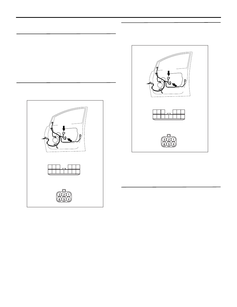
Step 2. Connector check: Connector check: F-05
power window main switch connector and F-16
power window motor (front: RH) connector
Q: Is the check result normal?
YES :
Go to Step 3.
NO :
Repair the connector.
Step 3. Check the wiring harness from F-16
power window motor (front: RH) connector
terminal Nos.1 and 3 to F-05 power window main
switch connector terminal Nos. 7 and 1.
• Check the input and output lines for open or short
circuit.
Q: Is the check result normal?
YES :
Go to Step 4.
NO :
Repair the wiring harness.
Step 4. Retest the system.
After the power window main switch is replaced,
check that the driver's door power window can be
operated by the power window main switch.
(1) Replace the power window main switch.
(2) Check that the driver's power window works by
means of the power window main switch.
Q: Is the check result normal?
YES :
The trouble can be an intermittent
malfunction (Refer to GROUP 00
− How to
Cope with Intermittent Malfunction
NO :
Replace the power window motor (front:
LH).
AC310214
AC310214
AB
Connectors: F-05, F-16
Harness side
<RHD>
10
1
6
14
5
12
13
4
11
7
2
3
8
9
F-05(B)
F-16(B)
F-05
F-16
Harness side
AC310214
AC310214
AB
Connectors: F-05, F-16
Harness side
<RHD>
10
1
6
14
5
12
13
4
11
7
2
3
8
9
F-05(B)
F-16(B)
F-05
F-16
Harness side