Mersedes Maybach S-Class. Service Manual - part 20
Vehicles with individual seats and center con-
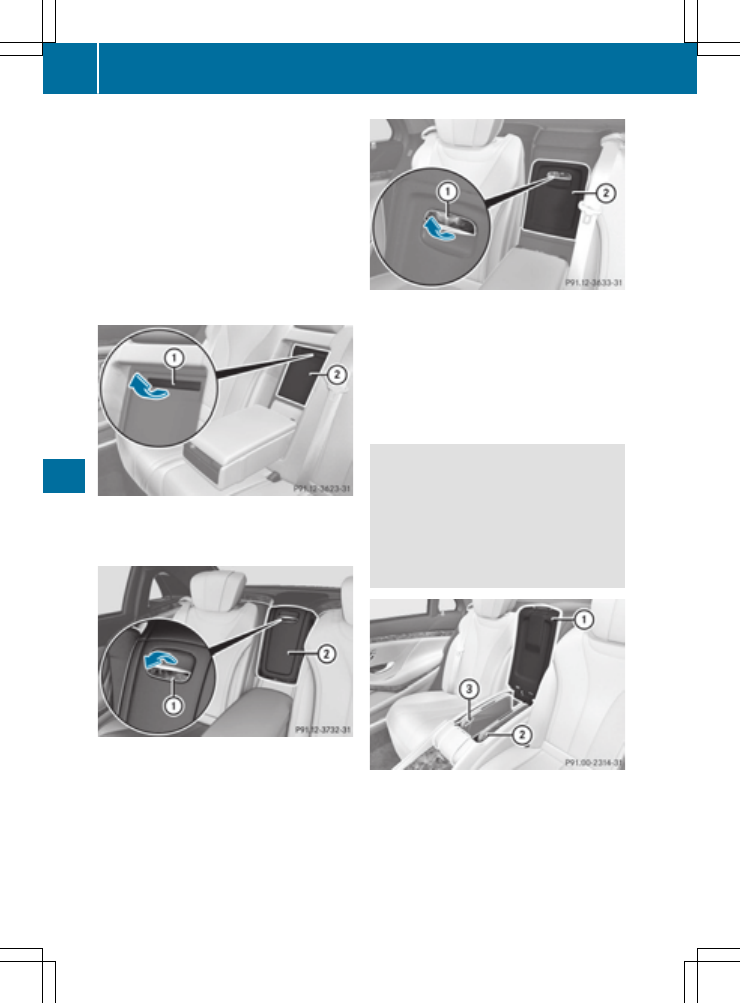
sole in the rear
X
Pull up on handle : and fold the armrest
upwards.
Depending on the vehicle's equipment, a USB
port, an AUX-IN jack, a mobile phone bracket or
a 115 V or 230 V socket are installed in the
stowage compartment.
Stowage box in the rear seat backrest
!
Do not sit on or support your body weight on
the rear seat armrest when it is folded down,
as you could otherwise damage it.
Vehicles with a rear bench seat:
X
To open: fold down the rear armrest.
X
Pull handle : and fold down cover ;.
Vehicles with electrically adjustable outer seats:
X
To open: fold down the rear armrest.
X
Pull handle : and fold down cover ;.
Vehicles with individual seats and center con-
sole in the rear:
X
To open: fold down the rear armrest.
X
Pull handle : and fold down cover ;.
Depending on the vehicle's equipment, a DVD
player is installed instead of a stowage com-
partment.
Folding table
G
WARNING
If the folding table is folded out while the vehi-
cle is in motion, passengers can be thrown
against it, particularly in the event of an acci-
dent, heavy braking or a sudden change of
direction. There is a risk of injury.
Fold the folding table away before each jour-
ney.
X
To fold out: open rear armrest :
(
Y
page 327).
X
Pull the folding table forwards and upwards by
recess ; or = and swing outwards.
X
Fold the table panels apart.
X
To fold in: fold the table panels together and
swing in the folding table.
328
Stowage areas
Stow
age
and
features