Mercedes-Benz Sprinter / Dodge Sprinter. Manual - part 504


  Index      Mercedes     Mercedes-Benz Sprinter / Dodge Sprinter - service repair manual 2006 year


Search            


Content   ..  502  503  504  505   ..


Mercedes-Benz Sprinter / Dodge Sprinter. Manual - part 504


AMBIENT TEMPERATURE SEN-
SOR

DESCRIPTION

The ambient air temperature sensor is a variable

resistor that monitors the air temperature outside of
the vehicle. The ambient air temperature sensor is
connected to the instrument cluster through a two-
wire harness lead and connector of the vehicle elec-
trical system (Fig. 13). The instrument cluster sends
out a message on the CAN bus to the ATC control
module which uses the sensor data to maintain opti-
mum cabin temperature levels.

The ambient air temperature sensor is mounted to

the front licence plate bracket by three integral
retaining tabs.

OPERATION

The ambient temperature sensor is a variable

resistor that operates on a five-volt reference signal
sent to it by the instrument cluster. The resistance in
the sensor changes as temperature changes. Based
upon the resistance in the sensor, the instrument
cluster sends the ATC control module a specific volt-
age on the temperature sensor signal circuit, which
is programmed to correspond to a specific tempera-
ture.

The ambient temperature sensor is diagnosed

using the DRBIII

t scan tool. Refer to Body Diagnos-

tic Procedures.

The

ambient

temperature

sensor

cannot

be

adjusted or repaired and, if faulty or damaged, it
must be replaced.

REMOVAL

(1) Disconnect and isolate the battery negative

cable.

(2) Remove the front license plate bracket (Refer

to

23

-

BODY/EXTERIOR/LICENSE

PLATE

BRACKET - REMOVAL).

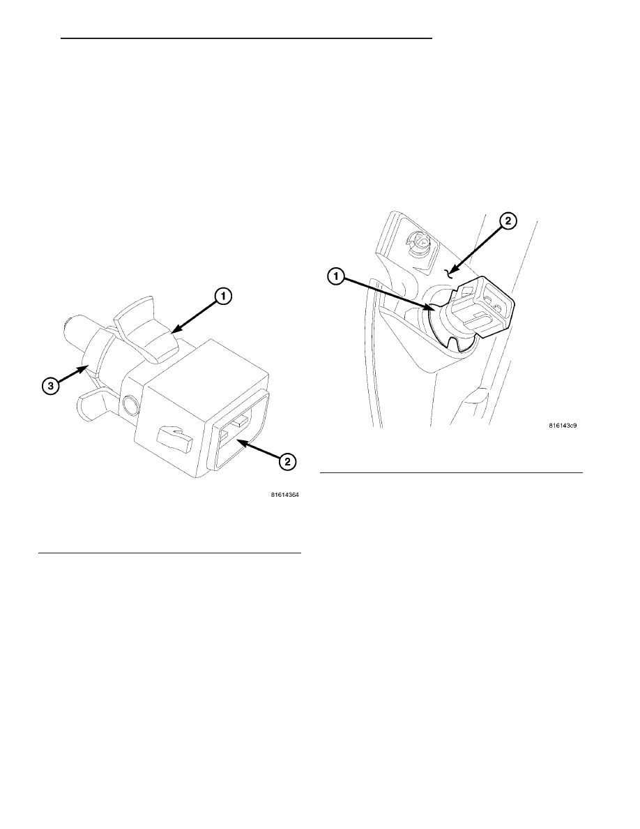
(3) Disconnect the wire harness connector from the

ambient temperature sensor (Fig. 14).

(4) Disengage

the

sensor

retaining

tabs

and

remove the ambient temperature sensor from the
front license plate bracket.

INSTALLATION

(1) Install the ambient temperature sensor onto

the front license plate bracket. Make sure the retain-
ing tabs are fully engaged.

(2) Connect the wire harness connector to the

ambient temperature sensor.

(3) Install the front license plate bracket (Refer to

23 - BODY/EXTERIOR/LICENSE PLATE BRACKET
- INSTALLATION).

(4) Reconnect the battery negative cable.

BLOWER MOTOR RESISTOR

DESCRIPTION

This temperature control system uses a blower

motor resistor (Fig. 15). The blower motor resistor is
mounted to the top of ventilation housing located in
the engine compartment. The blower motor resistor
consists of a molded plastic mounting plate with an
integral retaining tab and wire connector receptacle.
Concealed behind the mounting plate are coiled resis-
tor wires contained within a ceramic heat sink.

Fig. 13 Ambient Air Temperature Sensor

1 - AMBIENT TEMPERATURE SENSOR
2 - WIRE HARNESS CONNECTOR
3 - RETAINING TABS (3)

Fig. 14 Ambient Temperature Sensor

1 - AMBIENT TEMPERATURE SENSOR
2 - FRONT LICENSE PLATE BRACKET

VA

CONTROLS-FRONT

24 - 17

The blower motor resistor is accessed for service

without removing any other components.

OPERATION

The blower motor resistor block has multiple resis-

tor wires. Each resistor wire changes the resistance
in the blower motor current path to change the
blower motor speed. The blower motor switch directs
the current through the correct resistor wire to
obtain the selected speed.

With the blower motor switch in the lowest speed

position, voltage for the motor is applied through all
of the resistor wires. Each higher speed selected with
the blower motor switch applies the blower motor
current path through fewer of the resistor wires,
increasing the blower motor speed. When the blower
motor switch is in the highest speed position, the
blower motor resistor is bypassed and the blower
motor circuit receives a direct path to battery volt-
age.

The blower motor resistor block cannot be repaired

and, if faulty or damaged, it must be replaced.

DIAGNOSIS AND TESTING

BLOWER MOTOR RESISTOR

NOTE: For circuit descriptions and diagrams, refer
to the appropriate wiring information. The wiring
information includes wiring diagrams, proper wire
and connector repair procedures, further details on
wire harness routing and retention, as well as pin-
out and location views for the various wire harness
connectors, splices and grounds.

(1) Disconnect and isolate the negative battery

cable.

(2) Disconnect the wire harness connector from the

blower motor resistor.

(3) Check for continuity between each of the

blower motor switch input terminals of the resistor
and the resistor output terminal. In each case there
should be continuity. If OK, repair the wire harness
circuits between the blower motor switch and the
blower motor resistor or blower motor as required. If
not OK, replace the faulty blower motor resistor.

REMOVAL

(1) Disconnect and isolate the negative battery

cable.

(2) Depress the locking tab and remove the blower

motor resistor from the ventilation housing by sliding
the resistor inboard (Fig. 16).

(3) Depress the two locking tabs and disconnect

the wire harness connector from the blower motor
resistor.

(4) Remove the blower motor resistor from the

engine compartment.

INSTALLATION

(1) Connect the wire harness connector to the

blower motor resistor and engage the two locking
tabs.

(2) Install the blower motor resistor into the ven-

tilation housing and engage the locking tab. The
housing is indexed to allow mounting in only one
position.

(3) Reconnect the negative battery cable.

Fig. 15 Front Blower Motor Resistor

1 - MOUNTING PLATE
2 - WIRE CONNECTOR RECEPTACLE
3 - CERAMIC HEAT SINK

Fig. 16 Blower Motor Resistor Block

1 - BLOWER MOTOR RESISTOR
2 - ELECTRICAL CONNECTOR
3 - VENTILATION HOUSING

24 - 18

CONTROLS-FRONT

VA

BLOWER MOTOR SWITCH

DESCRIPTION

The blower motor is controlled by a thumbwheel-

type blower motor control, mounted in the A/C-heater
control (Fig. 17). The switch allows the selection of
four blower motor speeds with the ignition switch in
the On position.

NOTE: The blower motor will operate only at the
lowest speed when the Residual Engine Heat Utili-
zation (REST) function is selected, regardless of the
blower speed setting on the A/C-heater control.

OPERATION

When the ignition is turned to On, the integral

blower motor switch within the ATC A/C-heater con-
trol supplies power to the blower motor switch. The
switch directs power to the individual blower driver
circuits through the blower motor resistor block to
the blower motor and then to ground.

The blower motor switch cannot be adjusted or

repaired, and if faulty or damaged, the A/C-heater
control must be replaced (Refer to 24 - HEATING &
AIR

CONDITIONING/CONTROLS/A/C

HEATER

CONTROL - REMOVAL).

DIAGNOSIS AND TESTING

BLOWER MOTOR SWITCH

The blower motor switch can be diagnosed by using

the DRBIII

t scan tool. Refer to Body Diagnostic Pro-

cedures. For circuit descriptions and diagrams, refer
to the appropriate wiring information.

EVAPORATOR TEMPERATURE
SENSOR

DESCRIPTION

The evaporator temperature sensor measures the

temperature of the conditioned air downstream of the
A/C evaporator (Fig. 18). The evaporator temperature
sensor is an electrical thermistor within a molded
plastic case that is inserted into the HVAC housing
near the coldest point of the A/C evaporator. Two ter-
minals within the connector receptacle connect the
sensor to the vehicle electrical system through a wire
lead and connector of the HVAC wire harness.

The external location of the evaporator tempera-

ture sensor allows the sensor to be removed or
installed without disturbing the refrigerant in the
A/C system.

OPERATION

The evaporator temperature sensor monitors the

temperature of the A/C evaporator. The sensor will
change its internal resistance in response to the tem-
peratures it monitors. The A/C-heater control is con-
nected to the sensor through a sensor ground circuit
and a sensor signal circuit. As the evaporator tem-
perature increases, the resistance of the sensor
decreases and the voltage monitored by the A/C-
heater control decreases. The A/C-heater control uses
this monitored voltage reading to an indication of the
evaporator temperature. The A/C-heater control is
programmed to respond to this input by cycling the
A/C compressor clutch off if the evaporator tempera-
ture sensor reads between 1° C (33° F) and 3.5° C
(38° F) to protect the A/C evaporator from freezing.

Fig. 17 A/C-Heater Control

Fig. 18 Sensor-Evaporator Temperature

1 - EVAPORATOR TEMPERATUE SENSOR
2 - A/C EVAPORATOR
3 - HVAC HOUSING
4 - WIRE CONNECTOR

VA

CONTROLS-FRONT

24 - 19

The external location of the sensor allows the sensor
to be removed or installed without disturbing the
refrigerant in the A/C system.

The evaporator temperature sensor is diagnosed by

performing the ATC Function Test using a DRBIII

t

scan tool. Refer to Body Diagnostic Procedures.

The evaporator temperature sensor cannot be

adjusted or repaired and, if faulty or damaged, it
must be replaced.

REMOVAL

(1) Disconnect and isolate the negative battery

cable.

(2) Remove the radio (Refer to 8 - ELECTRICAL/

AUDIO/RADIO - REMOVAL).

(3) Remove glove compartment.
(4) Remove cover from instrument cluster (Refer to

23 - BODY/INSTRUMENT PANEL/INSTRUMENT
PANEL TOP COVER - REMOVAL).

(5) Remove the instrument cluster (Refer to 8 -

ELECTRICAL/INSTRUMENT

CLUSTER

-

REMOVAL).

(6) Remove passenger side airbag.
(7) Remove cover above air nozzle on passenger

side.

(8) Remove speaker.
(9) Remove center section of instrument panel.
(10) Remove A/C-heater control from the instru-

ment panel (Refer to 24 - HEATING & AIR CONDI-
TIONING/CONTROLS/A/C HEATER CONTROL -
REMOVAL).

(11) Remove instrument panel top section.
(12) Remove electrical connections.
(13) Remove air bezels from instrument panel.
(14) Disconnect the wire harness connector from

evaporator temperature sensor (Fig. 19).

(15) Remove evaporator temperature sensor from

HVAC housing.

INSTALLATION

(1) Install the probe of the evaporator temperature

sensor between the fins of the A/C evaporator.

NOTE: The probe must not go into the same hole
(in the A/C evaporator ) that the probe was removed
from.

(2) Install the wire harness connector to the evap-

orator temperature sensor.

(3) Install the air bezels to the instrument panel.
(4) Install the electrical connections.
(5) Install the instrument panel top section (Refer

to 23 - BODY/INSTRUMENT PANEL/INSTRUMENT
PANEL TOP COVER - INSTALLATION).

(6) Install the A/C-heater control (Refer to 24 -

HEATING & AIR CONDITIONING/CONTROLS/A/C
HEATER CONTROL - INSTALLATION).

(7) Install the center section of the instrument

panel.

(8) Install the speaker (Refer to 8 - ELECTRICAL/

AUDIO/SPEAKER - INSTALLATION).

(9) Install the cover above the air nozzle on the

passenger side.

(10) Install the passenger side airbag.
(11) Install the instrument cluster (Refer to 8 -

ELECTRICAL/INSTRUMENT CLUSTER - INSTAL-
LATION).

(12) Install the cover to the instrument cluster.
(13) Install glove compartment.
(14) Install the radio (Refer to 8 - ELECTRICAL/

AUDIO/RADIO - INSTALLATION).

(15) Reconnect the negative battery cable.

Fig. 19 Evaporator Temperature Sensor

1 - WIRE HARNESS CONNECTOR
2 - EVAPORATOR TEMPERATURE SENSOR

24 - 20

CONTROLS-FRONT

VA


Content   ..  502  503  504  505   ..