Mercedes-Benz Sprinter / Dodge Sprinter. Manual - part 439


  Index      Mercedes     Mercedes-Benz Sprinter / Dodge Sprinter - service repair manual 2006 year


Search            


Content   ..  437  438  439  440   ..


Mercedes-Benz Sprinter / Dodge Sprinter. Manual - part 439


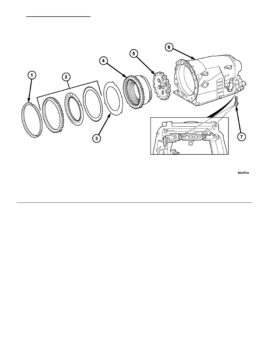
(29) Remove multiple-disc pack B3 (2) (Fig. 47)

and spring washer (3) by removing snap-ring (1) in
transmission housing. To facilitate removal of the
snap-ring (1), compress the multiple-disc pack B3 (2).
Note which clutch disc is removed just prior to the
spring washer (3) for re-assembly. If the clutch discs
are re-used, this disc must be returned to its original
position on top of the spring washer.

(30) Unscrew Torx socket bolts (7) (Fig. 47).
(31) Remove multiple-disc holding clutch B2 (4)

(Fig. 47) from transmission housing. The externally
toothed disc carrier for multiple-disc holding clutch
B2 is also the piston for multiple-disc holding clutch
B3.

(32) Remove parking lock gear (5) (Fig. 47).

Fig. 47 Remove B2, B3, and Parking Gear

1 - SNAP-RING

5 - PARK GEAR

2 - HOLDING CLUTCH B3 DISCS

6 - TRANSMISSION HOUSING

3 - SPRING WASHER

7 - BOLTS - M8X60

4 - HOLDING CLUTCH B2

VA

AUTOMATIC TRANSMISSION NAG1 - SERVICE INFORMATION

21 - 51

ASSEMBLY

(1) Insert parking lock gear (5) (Fig. 48).
(2) Install multiple-disc holding clutch B2 (4) in

transmission housing (6) (Fig. 48).

(3) Screw in both Torx socket bolts (7). Tighten the

bolts to 16 N·m (141 in.lbs.).

Fig. 48 Install B2, B3, and Parking Gear

1 - SNAP-RING

5 - PARK GEAR

2 - HOLDING CLUTCH B3 DISCS

6 - TRANSMISSION HOUSING

3 - SPRING WASHER

7 - BOLTS - M8X60

4 - HOLDING CLUTCH B2

Fig. 49 Measure B3 Clutch Clearance

1 - OUTER DISC - 6.5 MM
(0.256 IN.)

5 - PISTON

2 - OUTER DISCS - 1.8 MM
(0.071 IN.)

6 - FRICTION DISCS

3 - OUTER DISCS - 1.8 MM
(0.071 IN.)

7 - SNAP-RING

4 - SPRING WASHER

8 - B3 DISC CARRIER

21 - 52

AUTOMATIC TRANSMISSION NAG1 - SERVICE INFORMATION

VA

NOTE: During the measurement the snap ring (7)
(Fig. 49) must contact the upper bearing surface of
the groove in the outer multiple-disc carrier (8).

NOTE: Pay attention to sequence of discs. If the
original clutch discs are reused, be sure to return
the disc identified on disassembly as belonging on
top of the spring washer (4) to its original location.
Place new friction multiple-discs in ATF fluid for
one hour before installing.

(4) Insert and measure spring washer (4) (Fig. 49)

and multiple-disc pack B3 (2, 6).

(a) Put multiple-discs for multiple-disc holding

clutch B3 together in the sequence shown in the
illustration and insert individually.

(b)

CAUTION: Apply only light pressure (less than 10 N
(3 lbs.) of force) to the clutch pack when measuring
the clutch clearance with the feeler gauge. Applying
excessive force to the clutch will give an incorrect
reading and lead to a transmission failure.Using a
feeler gauge, determine the play “L” at three points
between the snap ring (7) and outer multiple-disc
(1). B3 clutch clearance should be 1.0-1.4 mm
(0.039-0.055 in.). Adjust the clearance as necessary.

(c) Adjust with snap-ring (7), if necessary. Snap-

rings are available in thicknesses of 3.2 mm (0.126
in.), 3.5 mm (0.138 in.), 3.8 mm (0.150 in.), 4.1 mm
(0.162 in.), 4.4 mm (0.173 in.), and 4.7 mm (0.185
in.).

(5) Check that the K1 clutch feed hole (1) (Fig. 50)

in the inner hub of clutch B1 is free before installing
clutch B1.

Fig. 50 Check K1 Feed Hole

1 - K1 CLUTCH FEED HOLE

VA

AUTOMATIC TRANSMISSION NAG1 - SERVICE INFORMATION

21 - 53

(6) Place intermediate plate (3) on converter hous-

ing (2) and align.

NOTE: The intermediate plate can generally be used
several times. The plate must not be coated with
sealant

(7) Install the holding clutch B1 (5) (Fig. 51) onto

the

converter

housing

and

intermediate

plate.

Installed position of clutch B1 in relation to converter
housing is specified by a plain dowel pin in clutch B1
(arrow).

(8) Install the bolts to hold clutch B1 (5) (Fig. 51)

to the converter housing.

(9) Securely tighten multiple-disc holding clutch

B1 (5) on converter housing (2) to 10 N·m (88.5
in.lbs.).

(10) Install new torque converter hub seal (1) (Fig.

52) into the oil pump using Seal Installer 8902A.

(11) Install new oil pump outer o-ring seal onto oil

pump (Fig. 52).

Fig. 51 Install Holding Clutch B1 and Oil Pump

1 - BOLTS - M6X32

4 - BOLTS - M8X35

2 - CONVERTER HOUSING

5 - HOLDING CLUTCH B1

3 - INTERMEDIATE PLATE

6 - OIL PUMP

Fig. 52 Install New Oil Pump Seals

1 - INNER OIL SEAL
2 - OUTER OIL SEAL

21 - 54

AUTOMATIC TRANSMISSION NAG1 - SERVICE INFORMATION

VA


Content   ..  437  438  439  440   ..