Mercedes-Benz Sprinter / Dodge Sprinter. Manual - part 413
(4) Fill fuel tank with fresh diesel fuel.
(5) Drain and remove the fuel filter. (Refer to 14 -
FUEL SYSTEM/FUEL DELIVERY/FUEL FILTER /
WATER SEPARATOR - REMOVAL)
(6) Install a new fuel filter. (Refer to 14 - FUEL
SYSTEM/FUEL DELIVERY/FUEL FILTER / WATER
SEPARATOR - INSTALLATION)
(7) Check the engine control module for any diag-
nostic trouble codes (DTCs). Record and clear any
DTCs that are present.
(8) Start and run the engine. Run the engine for
up to 15 minutes to allow time for any DTCs to reset
and shut off the engine.
(9) Check the engine control module for any diag-
nostic trouble codes (DTCs). Record any DTCs that
are present. Refer to the appropriate engine electrical
diagnostics to diagnose any DTCs that were set.
CAUTION: With the high pressure fuel system in
this vehicle, any residual contaminated fuel will be
removed very quickly. Shut off the engine immedi-
ately if signs of engine damage are noted.
The engine should then be evaluated to determine
if the contaminated fuel has caused any damage to
the fuel system and/or engine. Indicators that the
fuel system has been damaged include the following:
• Unstable fuel rail pressure. This can manifest
itself as instability of idle speeds, excessive under-
shoot/overshoot
at
engine
start-up,
or
excessive
undershoot/overshoot when the engine operating con-
ditions change. A typical engine response to a large
rail pressure undershoot would be a decrease in
engine speed or engine stall.
• Excessive noise from the engine. This could indi-
cate poor rail pressure control or the inability of the
injection system to inject the proper amount of fuel.
• Excessive smoke (black or white). This could
indicate the inability of the fuel system to inject the
proper amount of fuel.
NOTE: If any of these conditions are exhibited after
cleaning the fuel system, proceed to the appropri-
ate engine electrical diagnostic information. Repair
the fuel system and/or engine as necessary.
SPECIFICATIONS
TORQUE
DESCRIPTION
N·m
Ft. Lbs.
In. Lbs.
FUEL TANK MOUNTING NUTS
15 - 17
11 - 13
-
FUEL TANK MODULE LOCKRING (LOCK-
NUT)
60
44
-
PRESSURE CONTROL VALVE NUT TO
FUEL RAIL (2 STAGES)
60, loosen 90°, re-
tighten to 80
44, loosen 90°, re-
tighten to 59
-
SPECIAL TOOLS
FUEL SYSTEM
SPECIAL TOOL CROSS REFERENCE CHART
MB
TOOL #
MILLER
TOOL #
DESCRIPTION
N/A
5069-2
FUEL GAUGE
N/A
6856
SPANNER WRENCH
N/A
9068
FUEL GAUGE ADAPTER
N/A
9285
FUEL LINE WRENCH
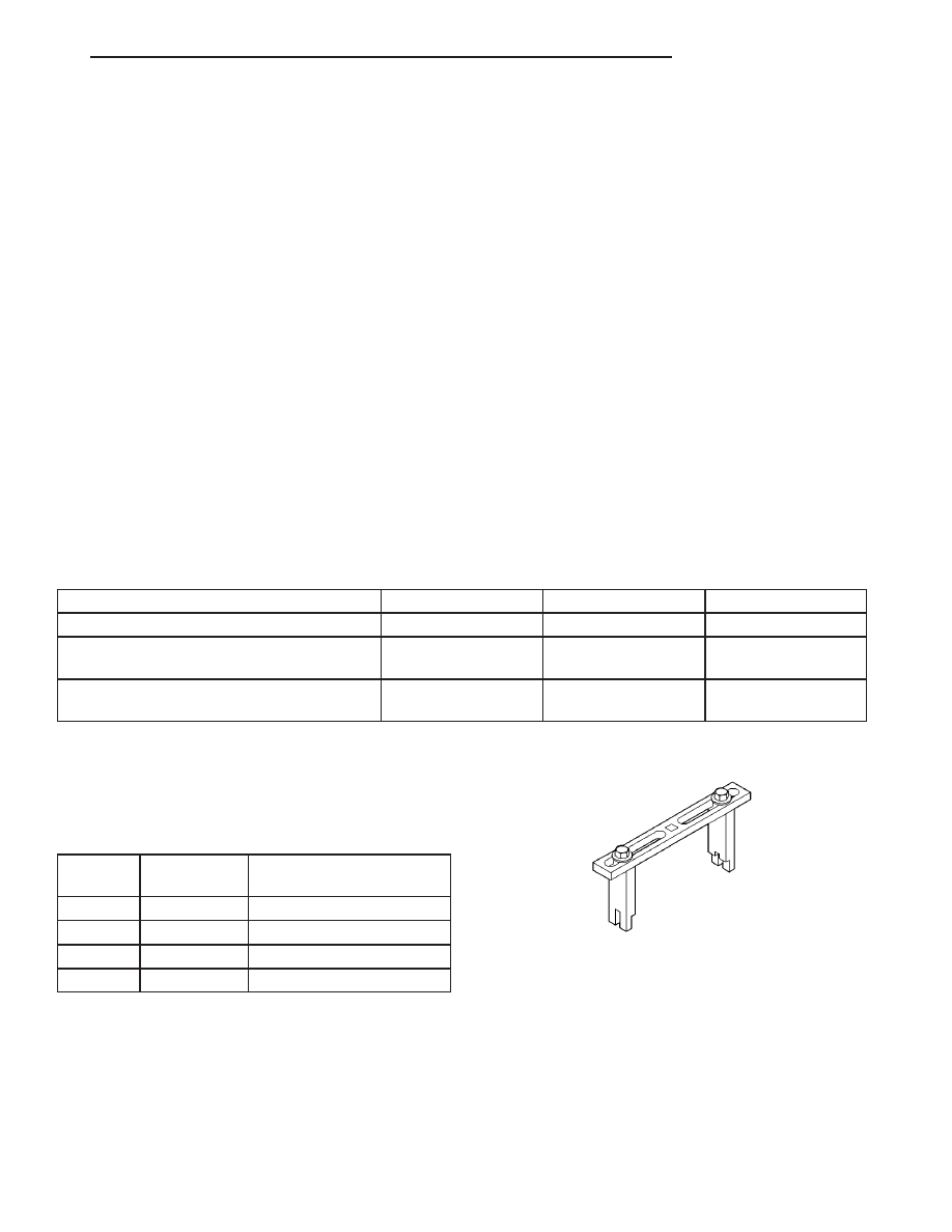
SPANNER WRENCH-6856
VA
FUEL DELIVERY
14 - 9