Mercedes-Benz Sprinter / Dodge Sprinter. Manual - part 118
Symptom List:
P1482-GLOW PLUG MODULE - COMMUNICATION ERROR
P2537-GLOW PLUG CONTROL CIRCUIT PREGLOW FAULT
P2537-GLOW PLUG CONTROL CIRCUIT PREGLOW SHORT TO
GROUND
P2537-GLOW PLUG CONTROL CIRCUIT PREGLOW SHORT TO
VOLTAGE
Test Note:
All symptoms listed above are diagnosed using the same tests.
The title for the tests will be P1482-GLOW PLUG MODULE -
COMMUNICATION ERROR.
POSSIBLE CAUSES
ENGINE CONTROL MODULE
GLOW PLUG CONTROL SIGNAL CIRCUIT OPEN
GLOW PLUG CONTROL SIGNAL CIRCUIT SHORTED TO GROUND
GLOW PLUG CONTROL SIGNAL CIRCUIT SHORTED TO VOLTAGE
GLOW PLUG MODULE
INTERMITTENT CONDITION
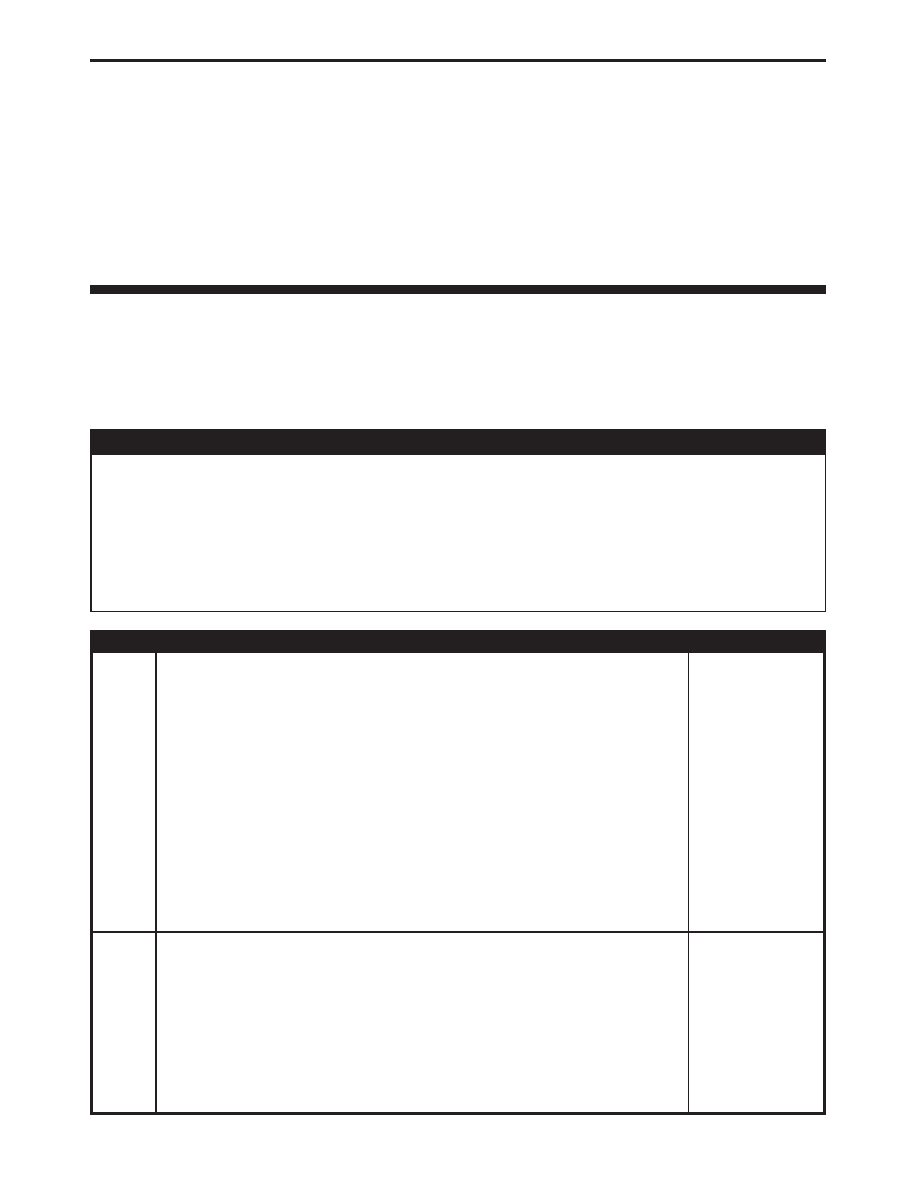
TEST
ACTION
APPLICABILITY
1
NOTE: If the ECM detects and stores a DTC, the ECM also stores the
engine/vehicle operating conditions under which the DTC was set. Some of
these conditions are displayed on the DRB at the same time the DTC is
displayed.
NOTE: Before erasing stored DTCs, record these conditions. Attempting to
duplicate these conditions may assist when checking for an active DTC.
Turn the ignition on.
With the DRB, erase ECM DTCs.
Perform several engine run cycles, turning the ignition off for at least 20 seconds
between each engine run cycle.
Turn the ignition on.
With the DRB, read ECM DTCs.
Did this DTC set again?
All
Yes
→ Go To 2
No
→ Go To 6
2
Turn the ignition off.
Disconnect the Glow Plug Module harness connectors.
Disconnect the ECM harness connectors.
Measure the resistance of the Glow Plug Control Signal circuit.
Measure the resistance of the Glow Plug Module Control circuit.
Is the resistance below 10.0 ohms?
All
Yes
→ Go To 3
No
→ Repair the Glow Plug Control Signal circuit for an open.
Perform ROAD TEST VERIFICATION - VER-2.
80
DRIVEABILITY - DIESEL