Mercedes-Benz Sprinter / Dodge Sprinter. Manual - part 100
3.3.4
HANDLING NO TROUBLE CODE
PROBLEMS
After reading Section 3.0 (System Description
and Functional Operation), you should have a bet-
ter understanding of the theory and operation of the
on-board diagnostics and how this relates to the
diagnosis of a vehicle that may have a driveability-
related symptom or complaint. When there are no
trouble codes present, refer to the no trouble code
(*) tests.
3.4
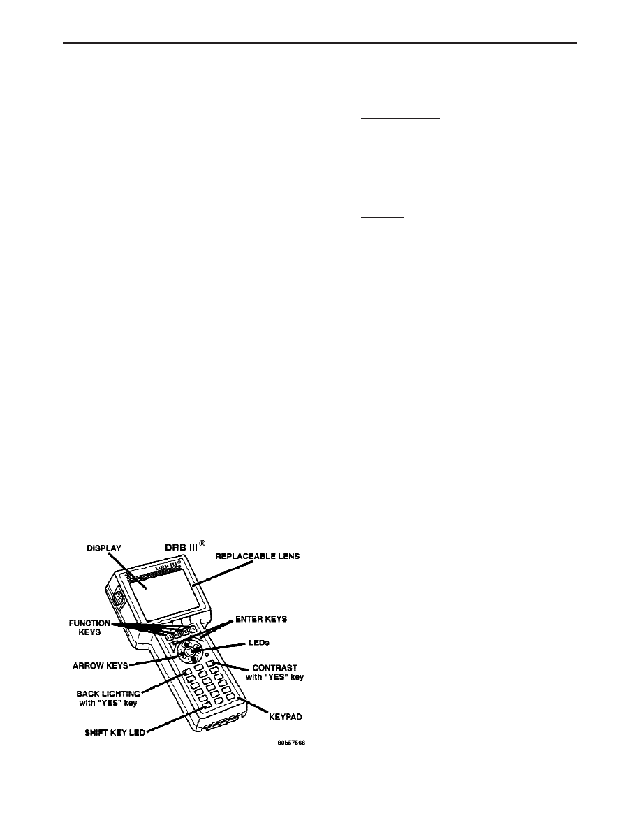
USING THE DRBIII
T
Refer to the DRBIII
t user’s guide for instructions
and assistance with reading the DTCs, erasing the
DTCs, lab scope usage and other DRBIII
t func-
tions.
3.4.1
DRBIII
T DOES NOT POWER UP
If the LEDs do not light or no sound is emitted at
start up, check for loose cable connections or a bad
cable. Check the vehicle battery voltage at data link
connector cavity 16. A minimum of 11.0 volts is
required to adequately power the DRBIII
t. Check
for proper ground connection at data link connector
cavities 4 and 5.
If all connections are proper between the
DRBIII
t and the vehicle or other devices, and the
vehicle battery is fully charged, an inoperative
DRBIII
t may be the result of a faulty cable or
vehicle wiring. For a blank screen, refer to the
appropriate diagnostic manual.
3.4.2
DISPLAY IS NOT VISIBLE
Low temperatures will affect the visibility of the
display. Adjust the contrast to compensate for this
condition.
4.0
DISCLAIMERS, SAFETY,
WARNINGS
4.1
DISCLAIMERS
All information, illustrations and specifications
contained in this manual are based on the latest
information available at the time of publication.
The right is reserved to make changes at any time
without notice.
4.2
SAFETY
4.2.1
TECHNICIAN SAFETY INFORMATION
WARNING: HIGH-PRESSURE FUEL LINES
DELIVER DIESEL FUEL UNDER EXTREME
PRESSURE FROM THE INJECTION PUMP TO
THE FUEL INJECTORS. THIS MAY BE AS
HIGH AS
23,200
PSI
(1600
BAR).
USE
EXTREME
CAUTION
WHEN
INSPECTING
FOR HIGH-PRESSURE FUEL LEAKS. FUEL
UNDER THIS AMOUNT OF PRESSURE CAN
PENETRATE
SKIN
CAUSING
PERSONAL
INJURY
OR
DEATH.
INSPECT
FOR
HIGH-PRESSURE
FUEL
LEAKS
WITH
A
SHEET OF CARDBOARD. WEAR SAFETY
GOGGLES AND ADEQUATE PROTECTIVE
CLOTHING
WHEN
SERVICING
FUEL
SYSTEM.
WARNING: ENGINES PRODUCE CARBON
MONOXIDE THAT IS ODORLESS, CAUSES
SLOWER REACTION TIME AND CAN LEAD
TO SERIOUS INJURY. WHEN THE ENGINE IS
OPERATING, KEEP SERVICE AREA WELL
VENTILATED OR ATTACH THE VEHICLE
EXHAUST SYSTEM TO THE SHOP EXHAUST
REMOVAL SYSTEM.
Set the parking brake and block the wheels before
testing or repairing the vehicle. It is especially
important to block the wheels on front wheel drive
vehicles; the parking brake does not hold the drive
wheels.
When servicing a vehicle, always wear eye pro-
tection and remove any metal jewelry such as
watchbands or bracelets that might make electrical
contact.
When diagnosing powertrain system problems, it
is important to follow approved procedures where
applicable. These procedures can be found in the
8
GENERAL INFORMATION