Mercedes-Benz ML320. Manual - part 323


  Index      Mercedes     Mercedes-Benz ML320 - service repair manual 1997-2005 year


Search            


Content   ..  321  322  323  324   ..


Mercedes-Benz ML320. Manual - part 323


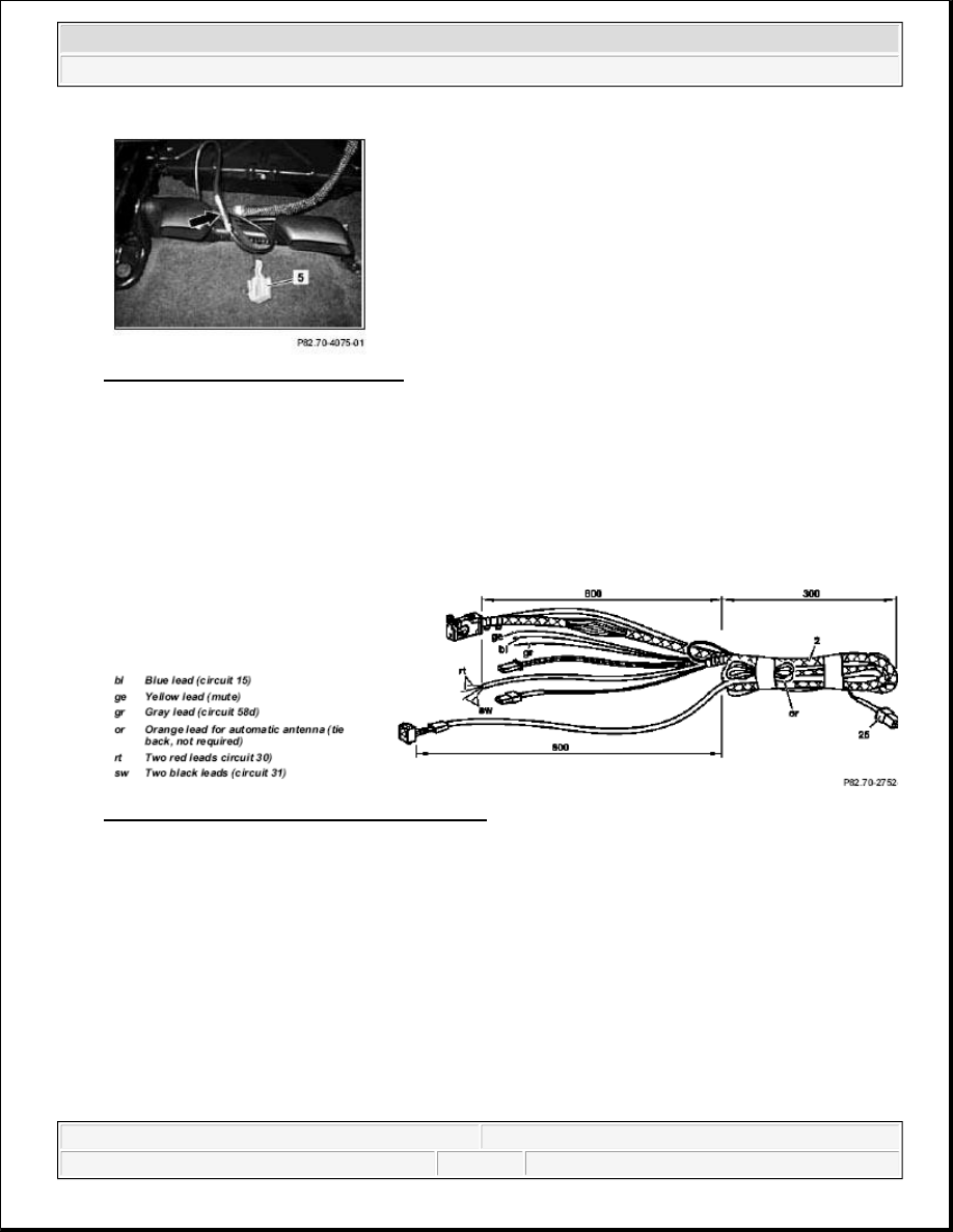
Fig. 366: Identifying Connection Plug 

RETROFIT WIRING HARNESS - AZ82.70-P-0001-04C 

Model 163 as of 1.12.99 up to 31.8.00 for Nokia 6090 fixed installation CTEL  

1. Prepare telephone wiring harness (2) as shown in figure.  

2. Tie back audio line-out cable with 4-pin connector (25) (is not required).  

3. Expose two red (rt) and two black (sw) cables. 

Fig. 367: Identifying Telephone Wiring Harness 

4. Unlock catch (arrows) of connector (21) one detent.  

5. Fit cable terminals (22) to the red (rt) leads and insert into chambers 3 and 9 of the connector (21).  

6. Fit cable terminals (22) to the black (sw) leads and insert into chambers 4 and 6.  

7. Insulate orange cable and tie back (is not required).  

8. Fit cable terminal (22) to blue (bl) lead and insert into chamber 5.  

9. Fit cable terminal (22) to yellow (ge) lead and insert into chamber 2.  

10. Fit cable terminal (22) to gray (gr) lead and insert into chamber 7.  

11. Lock connector (21). 


2001 Mercedes-Benz ML320 

1998-2005 ACCESSORIES & BODY, CAB Electrical System - Body - 163 Chassis


me 


Fig. 368: Identifying Lock Connector And Cable Terminals 

12. Insert wiring harness (2) into instrument panel working from the glove compartment. 

 The tied-back part must be placed below the strut (arrows) at the glove compartment. 

Fig. 369: Identifying Telephone Wiring Harness 

13. Connect telephone wiring harness (2) to adapter wiring harness (9).  

14. Check fuse (23) (a 10A fuse should be present). 


2001 Mercedes-Benz ML320 

1998-2005 ACCESSORIES & BODY, CAB Electrical System - Body - 163 Chassis


me 


Fig. 370: Identifying Fuse And Telephone Wiring Harness 

15. Connect adapter wiring harness (9) to radio wiring harness and insert into radio slot.  

16. Place microphone cable of telephone wiring harness (2) into radio slot. 

Fig. 371: Identifying Adapter Wiring Harness And Telephone Wiring Harness 

17. Route connection cable of telephone wiring harness (2) to telephone handset in middle tunnel as shown in 

figure. 

Fig. 372: Identifying Telephone Wiring Harness 

RETROFIT WIRING HARNESS - AZ82.70-P-0001-04D 

Model 163 as of 1.12.99 up to 31.8.00 for Nokia 3110 portable CTEL


2001 Mercedes-Benz ML320 

1998-2005 ACCESSORIES & BODY, CAB Electrical System - Body - 163 Chassis


me 


1. Shop-make wiring harness as specified in steps 2 to 6.  

2. Cut cables at connection adapter (20) to length of approx. 150 mm.  

3. Install terminal (22) on five free lead ends of connection adapter (20) (not to green lead).  

4. Release catch (arrows) at connector (21) one detent.  

5. Insert terminal of red (rt) lead into chamber 3 

Terminal of yellow (ge) lead into chamber 2 

Terminal of black (sw) lead into chamber 4 

Terminal of blue (bl) lead into chamber 5 

Insulate terminal of green (gn) lead and tie back (not required). 

Fig. 373: Identifying Lock Connector And Terminals 

6. Lock connector (21).  

7. Connect prefabricated wiring harness (8) to adapter wiring harness (9).  

8. Check fuse (23) (a 10A fuse should be present). 

Fig. 374: Identifying Adapter Wiring Harness And Fuse 

9. Connect adapter wiring harness (9) to radio wiring harness.  

10. Connect microphone cable and loudspeaker cable to hands-free unit (3).  

11. Plug in connection cable (2) and fit on cover (6). 


2001 Mercedes-Benz ML320 

1998-2005 ACCESSORIES & BODY, CAB Electrical System - Body - 163 Chassis


me 


Content   ..  321  322  323  324   ..