Mazda B2300 (2003 year). Instruction - part 9


  Index      Mazda     Mazda B2300 - instruction 2003 year in english


Search            


Content   ..  7  8  9  10   ..


Mazda B2300 (2003 year). Instruction - part 9


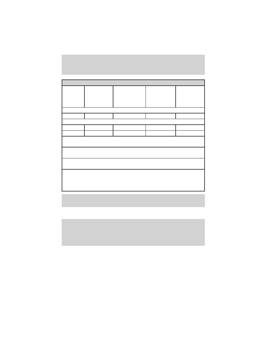
4x4 w/automatic transmission

Engine

Rear axle

ratio

Maximum

GCWR - kg

(lbs.)

Maximum

trailer

weight - kg

(lbs.)

Maximum

frontal area

of trailer -

m

2

(ft

2

)

Regular Cab

3.0L

All

3,402 (7,500)

1,742 (3,840)

4.64 (50)

Cab Plus/Cab Plus 4

3.0L

All

3,402 (7,500)

1,651 (3,640)

4.64 (50)

4.0L

All

4,309 (9,500)

2,504 (5,520)

4.64 (50)

For high altitude operation, reduce GCW by 2% per 300 meters (1, 000
ft.) of elevation.

For definition of terms used in this table, see Vehicle loading earlier
in this chapter.

To determine maximum trailer weight designed for your vehicle, see
Calculating the load earlier in this chapter.

Maximum trailer weight is shown. The combined weight of the
completed towing vehicle (including hitch, passengers and cargo) and
the loaded trailer must not exceed the Gross Combined Weight Rating
(GCWR).

WARNING: Do not exceed the GVWR or the GAWR specified on
the certification label.

The certifcation label is found on the driver’s door latch pillar.

WARNING: Towing trailers beyond the maximum recommended
gross trailer weight exceeds the limit of the vehicle and could
result in engine damage, transmission damage, structural
damage, loss of vehicle control, vehicle rollover and personal
injury.

Preparing to tow

Use the proper equipment for towing a trailer and make sure it is
properly attached to your vehicle. See your dealer or a reliable trailer
dealer if you require assistance.

Driving

134

Hitches

For towing trailers up to 907 kg (2,000 lb), use a weight carrying hitch
and ball which uniformly distributes the trailer tongue loads through the
underbody structure. Use a frame-mounted weight distributing hitch for
trailers over 907 kg (2,000 lb).

Do not install a single or multi-clamp type bumper hitch, or a hitch
which attaches to the axle. Underbody mounted hitches are acceptable if
they are installed properly. Follow the towing instructions of a reputable
rental agency.

Whenever a trailer hitch and hardware are removed, make sure all
mounting holes in the underbody are properly sealed to prevent noxious
gases or water from entering.

Safety chains

Always connect the trailer’s safety chains to the frame or hook retainers
of the vehicle hitch. To connect the trailer’s safety chains, cross the
chains under the trailer tongue and allow slack for turning corners.

If you use a rental trailer, follow the instructions that the rental agency
gives to you.

Do not attach safety chains to the bumper.

Trailer brakes

Electric brakes and manual, automatic or surge-type trailer brakes are
safe if installed properly and adjusted to the manufacturer’s
specifications. The trailer brakes must meet local and Federal
regulations.

WARNING: Do not connect a trailer’s hydraulic brake system
directly to your vehicle’s brake system. Your vehicle may not
have enough braking power and your chances of having a
collision greatly increase.

The braking system of the tow vehicle is rated for operation at the
GVWR not GCWR.

Trailer lamps

Trailer lamps are required on most towed vehicles. Make sure your
trailer lamps conform to local and Federal regulations. See your dealer or
trailer rental agency for proper instructions and equipment for hooking
up trailer lamps.

Driving

135

Using a step bumper

The optional step bumper is equipped with an integral hitch and requires
only a ball with a 19 mm (3/4 inch) shank diameter. The bumper has a
907 kg (2,000 lb.) trailer weight and 91 kg (200 lb.) tongue weight
capability.

The rated capacities (as shown in this guide) for trailer towing with the
factory bumper are only valid when the trailer hitch ball is installed
directly into the ball hole in the bumper. Addition of bracketry to either
lower the ball hitch position or extend the ball hitch rearward will
significantly increase the loads on the bumper and its attachments. This
can result in the failure of the bumper or the bumper attachments. Use
of any type of hitch extensions should be considered abuse.

Trailer tow connector

The trailer tow connector is located
under the rear bumper, on the
driver’s side of the vehicle.

Refer to the following chart for information regarding the
factory-equipped trailer tow connector:

Trailer tow connector

Color

Function

Comment

1. Dark Green

Trailer right-hand
turn signal

Circuit activated when brake
pedal is depressed or when
ignition is on and right-hand
turn signal is applied.

2. Yellow

Trailer left-hand turn
signal

Circuit activated when brake
pedal is depressed or when
ignition is on and left-hand
turn signal is applied.

1

2

3

4

Driving

136

Trailer tow connector

Color

Function

Comment

3. Tan/White

Tail lamp

Relay controlled circuit
activated when the park
lamps/headlamps are on.

4. White

Ground

Matching vehicle circuit
returns to battery’s negative
ground.

Driving while you tow

When towing a trailer:
• Turn off the speed control. The speed control may shut off

automatically when you are towing on long, steep grades.

• Consult your local motor vehicle speed regulations for towing a trailer.
• To eliminate excessive shifting, use a lower gear. This will also assist

in transmission cooling. (For additional information, refer to the
Driving with a 5–speed automatic transmission section in this
chapter.

• Anticipate stops and brake gradually.
• Do not exceed the GCWR rating or transmission damage may occur.

Servicing after towing

If you tow a trailer for long distances, your vehicle will require more
frequent service intervals. Refer to your service maintenance section for
more information.

Trailer towing tips

• Practice turning, stopping and backing up before starting on a trip to

get the feel of the vehicle trailer combination. When turning, make
wider turns so the trailer wheels will clear curbs and other obstacles.

• Allow more distance for stopping with a trailer attached.
• The trailer tongue weight should be 10–15% of the loaded trailer

weight.

• After you have traveled 80 km (50 miles), thoroughly check your

hitch, electrical connections and trailer wheel lug nuts.

• To aid in engine/transmission cooling and A/C efficiency during hot

weather while stopped in traffic, place the gearshift lever in P (Park)
(automatic transmission) or N (Neutral) (manual transmissions).

Driving

137

• Vehicles with trailers should not be parked on a grade. If you must

park on a grade, place wheel chocks under the trailer’s wheels.

Launching or retrieving a boat

Disconnect the wiring to the trailer before backing the trailer
into the water. Reconnect the wiring to the trailer after the
trailer is removed from the water.

When backing down a ramp during boat launching or retrieval:
• do not allow the static water level to rise above the bottom edge of

the rear bumper.

• do not allow waves to break higher than 15 cm (6 inches) above the

bottom edge of the rear bumper.

Exceeding these limits may allow water to enter vehicle components:
• causing internal damage to the components.
• affecting driveability, emissions and reliability.
Replace the rear axle lubricant any time the axle has been submerged in
water. Rear axle lubricant quantities are not to be checked or changed
unless a leak is suspected or repair required.

RECREATIONAL TOWING

Follow these guidelines if you have a need for recreational towing. An
example of recreational towing would be towing your vehicle behind a
motorhome. These guidelines are designed to ensure that your
transmission is not damaged.

4x2 equipped with a manual transmission:

Before you have your vehicle towed:
• Release the parking brake.
• Move the gearshift to the neutral position.
• Turn the key in the ignition to the OFF/UNLOCKED position.
• The maximum recommended speed is 88 km/h (55 mph).
• The maximum recommended distance is unlimited.
• The vehicle must be towed in the forward position to ensure no

damage is done to the internal transfer case components.

In addition, it is recommended that you follow the instructions
provided by the aftermarket manufacturer of the towing
apparatus if one has been installed.

Driving

138

4x2 equipped with automatic transmission and 4x4 vehicles:

4x2 vehicles with automatic transmissions or 4x4 vehicles with an
electronic-shift transfer case and automatic transmission, follow these
guidelines for recreational towing:
• Release the parking brake.
• Turn the key in the ignition to the OFF/UNLOCKED position.
• Place the transmission in N (Neutral).
• Do not exceed a distance of 80 km (50 miles).
• Do not exceed 56 km/h (35 mph) vehicle speed.
• The vehicle must be towed in the forward position to ensure no

damage is done to the internal transfer case components.

If a distance of 80 km (50 miles) or a speed of 56 km/h (35 mph) must
be exceeded, you must disconnect the front (4x4 only) and rear
driveshafts. Mazda recommends the driveshafts be removed/installed only
by a qualified technician. See your local dealer for driveshaft
removal/installation.

Improper removal/installation of the driveshaft can cause
transmission fluid or transfer case fluid loss, damage to the
driveshaft and internal transmission and transfer case
components.

CAMPER BODIES

Your pickup is not recommended for slide–in camper bodies.

Driving

139

HAZARD FLASHER

The hazard flasher is located on the
steering column, just behind the
steering wheel. The hazard flashers
will operate when the ignition is in
any position.

Push in the flasher control and all
front and rear direction signals will
flash. Press the flasher control again
to turn them off. Use it when your
vehicle is disabled and is creating a
safety hazard for other motorists.

Note: With extended use, the flasher may run down your battery.

FUEL PUMP SHUT-OFF SWITCH

FUEL

RESET

This device stops the electric fuel pump from sending fuel to the engine
when your vehicle has had a substantial jolt.

After an accident, if the engine cranks but does not start, this switch
may have been activated.

Roadside Emergencies

140

This switch is located in the front
passenger’s footwell, by the kick
panel access cover.

To reset the switch:

1. Turn the ignition OFF.

2. Check the fuel system for leaks.

3. If no leaks are apparent, reset

the switch by pushing in on the
reset button.

4. Turn the ignition ON.

5. Wait a few seconds and return

the key to OFF.

6. Make another check of leaks.

FUSES AND RELAYS

Fuses

If electrical components in the
vehicle are not working, a fuse may
have blown. Blown fuses are
identified by a broken wire within
the fuse. Check the appropriate
fuses before replacing any electrical
components.

Note: Always replace a fuse with one that has the specified amperage
rating. Using a fuse with a higher amperage rating can cause severe wire
damage and could start a fire.

15

Roadside Emergencies

141

Standard fuse amperage rating and color

COLOR

Fuse

rating

Mini

fuses

Standard

fuses

Maxi

fuses

Cartridge

maxi

fuses

Fuse link

cartridge

2A

Grey

Grey

3A

Violet

Violet

4A

Pink

Pink

5A

Tan

Tan

7.5A

Brown

Brown

10A

Red

Red

15A

Blue

Blue

20A

Yellow

Yellow

Yellow

Blue

Blue

25A

Natural

Natural

30A

Green

Green

Green

Pink

Pink

40A

Orange

Green

Green

50A

Red

Red

Red

60A

Blue

Yellow

70A

Tan

Brown

80A

Natural

Black

Passenger compartment fuse panel

The fuse panel is located on the
left-hand side of the instrument
panel facing the driver’s side door.
Pull the panel cover outward to
access the fuses.

Roadside Emergencies

142

To remove a fuse use the fuse puller tool provided.

The fuses are coded as follows:

Fuse/Relay

Location

Fuse Amp

Rating

Passenger Compartment Fuse Panel

Description

1

5A

Power mirror switch

2

10A

Daytime Running Lights (DRL), Back-up
lamps, Transmission, Passenger air bag
deactivation switch, Blower motor relay

3

7.5A

Left stop/turn trailer tow connector

4

Not used

5

15A

4x4 control module

6

2A

Brake pressure switch

7

7.5A

Right stop/turn trailer tow connector

8

Not used

9

7.5A

Brake pedal position switch

Roadside Emergencies

143

Fuse/Relay

Location

Fuse Amp

Rating

Passenger Compartment Fuse Panel

Description

10

7.5A

Speed control servo/amplifier assembly,
Generic Electronic Module (GEM), Shift
lock actuator, Turn signals, 4x4

11

7.5A

Instrument cluster, 4x4, Main light switch,
Central Security Module (CSM), Generic
Electronic Module (GEM)

12

Not used

13

20A

Brake pedal position switch

14

10A

Anti-lock Brake System (ABS) control
module

15

Not used

16

30A

Windshield wiper motor, Wiper HI/LO
relay, Wiper run/park relay

17

20A

Cigar lighter, Data Link Connector (DLC)

18

Not used

19

25A

Powertrain Control Module (PCM) power
diode, Ignition, PATS (Passive Anti-Theft
System)

20

7.5A

Generic Electronic Module (GEM), Radio

21

15A

Hazard flasher

22

20A

Auxiliary power socket

23

Not used

24

7.5A

Clutch Pedal Position (CPP) switch,
Starter interrupt relay

25

Not used

26

10A

Battery saver relay, Auxiliary relay box,
Restraint Central Module (RCM), Generic
Electronic Module (GEM), Instrument
cluster

27

Not used

28

7.5A

Generic Electronic Module (GEM), Radio

29

20A

Radio

Roadside Emergencies

144

Fuse/Relay

Location

Fuse Amp

Rating

Passenger Compartment Fuse Panel

Description

30

Not used

31

Not used

32

Not used

33

15A

Headlamps, Daytime Running Lamps
(DRL) module, Instrument cluster

34

Not used

35

15A

Horn relay (if not equipped with a Central
Security Module)

36

Not used

Power distribution box

The power distribution box is
located in the engine compartment.
The power distribution box contains
high-current fuses that protect your
vehicle’s main electrical systems
from overloads.

WARNING: Always disconnect the battery before servicing high
current fuses.

WARNING: To reduce risk of electrical shock, always replace
the cover to the Power Distribution Box before reconnecting
the battery or refilling fluid reservoirs.

If the battery has been disconnected and reconnected, refer to the
Battery section of the Maintenance and specifications chapter.

Roadside Emergencies

145

2.3L engine (if equipped)

The high-current fuses are coded as follows:

Fuse/Relay

Location

Fuse Amp

Rating

Power Distribution Box Description

1

50A**

I/P fuse panel

2

Not used

3

Not used

4

Not used

5

Not used

6

50A**

Anti-lock Brake System (ABS) pump
motor

7

30A*

Powertrain Control Module (PCM)

8

20A*

Central security module, Power door locks,
Remote entry

9

Not used

10

Not used

11

50A**

Starter relay, Ignition switch

12

20A*

Power windows

1

2

3

4

5

21

22

23

24

25

26

27

28

29

30

31

32

33

34

35

36

37

38

39

40

41

42

43

44

6

7

8

9

10

55

49

48

54

53

52

51

56

56 B

56 A

50

50 B

50 A

47

45

45 B

45 A

46

46 B

46 A

11

12

13

14

15

16

17

18

19

20

Roadside Emergencies

146

Fuse/Relay

Location

Fuse Amp

Rating

Power Distribution Box Description

13

Not used

14

Not used

15

Not used

16

40A**

Blower motor

17

20A**

Auxiliary cooling fan

18

Not used

19

Not used

20

Not used

21

10A*

PCM memory

22

Not used

23

20A*

Fuel pump motor

24

30A*

Headlamps

25

10A*

A/C clutch relay

26

Not used

27

Not used

28

30A*

ABS module

29

Not used

30

15A*

Trailer Tow

31

20A*

Foglamp, Daytime Running Lamps (DRL)

32

Not used

33

15A*

Park lamp, Central security module

34

Not used

35

Not used

36

Not used

37

Not used

38

10A*

Left headlamp low beam

39

Not used

40

Not used

41

20A*

Heated oxygen sensors

42

10A*

Right headlamp low beam

43

(Resistor)

Roadside Emergencies

147

Fuse/Relay

Location

Fuse Amp

Rating

Power Distribution Box Description

44

Not used

45A

Wiper HI/LO relay

45B

Wiper park/run relay

46A

Fuel pump relay

46B

Trailer tow relay

47

Starter relay

48

Auxiliary cooling fan relay

49

Not used

50

Not used

51

Not used

52

Not used

53

PCM Diode

54

PCM Relay

55

Blower motor relay

56A

A/C clutch relay

56B

Front washer pump relay

* Mini Fuses ** Maxi Fuses

Roadside Emergencies

148

3.0L and 4.0L engines (if equipped)

The high-current fuses are coded as follows:

Fuse/Relay

Location

Fuse Amp

Rating

Power Distribution Box Description

1

50A**

I/P fuse panel

2

Not used

3

Not used

4

Not used

5

Not used

6

50A**

Anti-lock Brake System (ABS) Pump
Motor

7

30A*

Powertrain Control Module (PCM)

8

20A*

Power door locks, Remote entry

9

Not used

10

Not used

11

50A**

Starter relay, Ignition switch

12

20A*

Power windows

13

20A*

4x4 motor

Roadside Emergencies

149


Content   ..  7  8  9  10   ..