Mazda B2300 Truck (2009 year). Instruction - part 12


  Index      Mazda     Mazda B2300 Truck - instruction 2009 year in english


Search            


Content   ..  10  11  12  13   ..


Mazda B2300 Truck (2009 year). Instruction - part 12


The fuses are coded as follows:
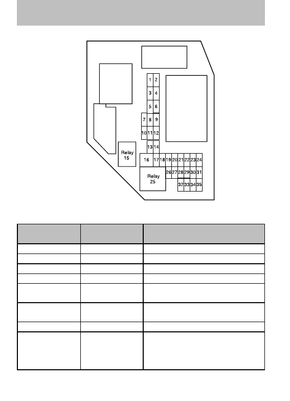
Fuse/Relay

Location

Fuse Amp

Rating

Passenger Compartment Fuse

Panel Description

1

5A

Instrument panel dimmer switch

2

10A

Trailer tow park lamps

3

10A

Right low beam headlamp

4

10A

Left low beam headlamp

5

5A

Windshield wiper module
(RUN/ACCY)

6

10A

Radio (RUN/ACCY), Door switch
illumination

7

Not used

8

10A

Restraints Control Module (RCM),
PADI (Passenger Air bag
Deactivation Indicator), Occupant
Classification Sensor (OCS)

2009 B-Series (mbs)
Owners Guide, 1st Printing
USA 
(fus)

Roadside Emergencies

184

Fuse/Relay

Location

Fuse Amp

Rating

Passenger Compartment Fuse

Panel Description

9

5A

Cluster air bag indicator

10

10A

Cluster (RUN/START), 4x4
module (RUN/START)

11

10A

Smart Junction Box (SJB) (Logic
power)

12

15A

Audiophile subwoofer amplifier,
Satellite radio

13

15A

Horn, Interior lamps

14

15A

High beam headlamp, High beam
indicator (cluster)

15

Not used

16

30A cartridge

fuse

Power windows

17

15A

Turn signals/Hazards

18

Not used

19

20A

Center High-Mounted Stop Lamp
(CHMSL)/Stop lamps

20

10A

Anti-lock Brake System (ABS)
module, Speed control module,
Back-up lamps, Overdrive cancel
switch, Electronic flasher
(turn/hazard)

21

5A

Starter relay coil

22

5A

Radio (START)

23

30A

Headlamps (low and high beam)

24

20A

Radio battery feed (B+)

25

Accessory relay (power windows)

26

2A

Redundant cruise switch

27

10A

Climate control blower relay/blend
doors

28

15A

4x4 module battery feed (B+)

2009 B-Series (mbs)
Owners Guide, 1st Printing
USA 
(fus)

Roadside Emergencies

185

Fuse/Relay

Location

Fuse Amp

Rating

Passenger Compartment Fuse

Panel Description

29

20A

Cigar lighter, Diagnostic connector
(OBD II)

30

5A

Power mirrors

31

20A

Front park lamps, Rear park
lamps, License plate lamps,
Dimmer switch, Trailer tow park
lamps

32

5A

Brake switch (logic), Brake-shift
interlock

33

5A

Instrument cluster battery feed
(B+)

34

20A

Power point

35

15A

Power locks

Power distribution box

The power distribution box is
located in the engine compartment.
The power distribution box contains
high-current fuses that protect your
vehicle’s main electrical systems
from overloads.

WARNING:

Always disconnect the battery before servicing

fuses.

WARNING:

To reduce risk of electrical shock, always replace

the cover to the Power Distribution Box before reconnecting the

battery or refilling fluid reservoirs.

If the battery has been disconnected and reconnected, refer to the
Battery section of the Maintenance and specifications chapter.

2009 B-Series (mbs)
Owners Guide, 1st Printing
USA 
(fus)

Roadside Emergencies

186

2.3L engine (if equipped)

The high-current fuses are coded as follows:

Fuse/Relay

Location

Fuse Amp

Rating

Power Distribution Box

Description

1

40A**

Passenger compartment fuse
panel

2

Not used

3

40A**

Passenger compartment fuse
panel

4

Not used

5

50A**

Passenger compartment fuse
panel

6

Not used

7

30A**

Starter solenoid

8

Not used

9

40A**

Ignition switch

10

Not used

11

30A**

Powertrain Control Module (PCM)
relay

2009 B-Series (mbs)
Owners Guide, 1st Printing
USA 
(fus)

Roadside Emergencies

187

Fuse/Relay

Location

Fuse Amp

Rating

Power Distribution Box

Description

12

Not used

13

30A**

Blower motor (climate control)

14

Not used

15

Not used

16

Not used

17

40A**

Anti-lock Brake System (ABS)
module

18

Not used

19

20A**

Engine fan

20

Not used

21

10A*

PCM keep alive power, Canister
purge valve solenoid

22

Not used

23

30A*

Fuel pump motor, Fuel injectors

24

Not used

25

10A*

A/C clutch solenoid

26

Not used

27

Not used

28

Not used

29

30A*

Wipers/washer

30

Not used

31

Not used

32

Not used

33

30A*

Anti-lock Brake System (ABS)
module

34

Not used

35

Not used

36

Not used

37

Not used

38

7.5A*

Trailer tow (right turn)

39

15A*

PCM power

2009 B-Series (mbs)
Owners Guide, 1st Printing
USA 
(fus)

Roadside Emergencies

188

Fuse/Relay

Location

Fuse Amp

Rating

Power Distribution Box

Description

40

Not used

41

10A*

Automatic transmission

42

7.5A*

Trailer tow (left turn)

43

20A*

Engine fan relay coil, A/C relay,
Engine sensors, VMV solenoid

44

15A*

Ignition coil, Capacitor

45A

Not used

45B

Not used

46A

Fuel pump relay, Fuel injectors
relay

46B

Not used

47

Engine fan relay

48

Starter relay

49

Not used

50

Not used

51

Not used

52

Not used

53

Not used

54

PCM relay

55

Blower relay

56A

A/C clutch solenoid relay

56B

Not used

* Mini Fuses ** Maxi Fuses

2009 B-Series (mbs)
Owners Guide, 1st Printing
USA 
(fus)

Roadside Emergencies

189

4.0L engines (if equipped)

The high-current fuses are coded as follows:

Fuse/Relay

Location

Fuse Amp

Rating

Protected Circuits

1

40A**

Passenger compartment fuse
panel

2

Not used

3

40A**

Passenger compartment fuse
panel

4

Not used

5

50A**

Passenger compartment fuse
panel

6

Not used

7

30A**

Starter solenoid

8

Not used

9

40A**

Ignition switch

10

Not used

11

30A**

Powertrain Control Module (PCM)
relay fuse

2009 B-Series (mbs)
Owners Guide, 1st Printing
USA 
(fus)

Roadside Emergencies

190

Fuse/Relay

Location

Fuse Amp

Rating

Protected Circuits

12

Not used

13

30A**

Blower motor (climate control)

14

Not used

15

Not used

16

Not used

17

40A**

Anti-lock Brake System (ABS)
module

18

Not used

19

Not used

20

Not used

21

10A*

PCM keep alive power, Canister
purge valve solenoid

22

Not used

23

30A*

Fuel pump motor, Fuel injectors

24

Not used

25

10A*

A/C clutch solenoid

26

Not used

27

20A*

4x4 module

28

Not used

29

30A*

Wipers/washer

30

Not used

31

15A*

Foglamps

32

Not used

33

30A*

Anti-lock Brake System (ABS)
module

34

Not used

35

Not used

36

Not used

37

Not used

38

7.5A*

Trailer tow (right turn)

39

15A*

PCM power

2009 B-Series (mbs)
Owners Guide, 1st Printing
USA 
(fus)

Roadside Emergencies

191

Fuse/Relay

Location

Fuse Amp

Rating

Protected Circuits

40

Not used

41

10A*

Automatic transmission

42

7.5A*

Trailer tow (left turn)

43

20A*

A/C relay coil, Engine sensors,
VMV solenoid, EGR solenoid,
Heated PCV

44

15A*

Ignition coil, Capacitor

45A

Not used

45B

Not used

46A

A/C clutch solenoid

46B

Not used

47

PCM relay

48A

Fuel pump relay, Fuel injectors
relay

48B

Fog lamp relay

51

Not used

52

Not used

53

Not used

54

Not used

55

Blower relay

56

Starter relay

* Mini Fuses ** Maxi Fuses

CHANGING THE TIRES

If you get a flat tire while driving:
• do not brake heavily.
• gradually decrease the vehicle’s speed.
• hold the steering wheel firmly.
• slowly move to a safe place on the side of the road.
Note:

The tire pressure monitoring system (TPMS) indicator light will

illuminate when the spare is in use. To restore the full functionality of
the monitoring system, all road wheels equipped with tire pressure
monitoring sensors must be mounted on the vehicle.

2009 B-Series (mbs)
Owners Guide, 1st Printing
USA 
(fus)

Roadside Emergencies

192

Have a flat serviced by an authorized dealer in order to prevent damage
to the TPMS sensor, refer to Changing tires with TPMS in the Tires,
Wheels and Loading 
chapter. Replace the spare tire with a road tire as
soon as possible.

WARNING:

The use of tire sealants may damage your Tire

Pressure Monitoring System and should not be used.

WARNING:

Refer to Tire Pressure Monitoring System

(TPMS) in the Tires, Wheels and Loading chapter for

important information. If the tire pressure monitor sensor
becomes damaged, it will no longer function.

Dissimilar spare tire/wheel information

WARNING:

Failure to follow these guidelines could result in an

increased risk of loss of vehicle control, injury or death.

If you have a dissimilar spare tire/wheel, then it is intended for
temporary use only. This means that if you need to use it, you should
replace it as soon as possible with a road tire/wheel that is the same size
and type as the road tires and wheels that were originally provided by
Mazda. If the dissimilar spare tire or wheel is damaged, it should be
replaced rather than repaired.

A dissimilar spare tire/wheel is defined as a spare tire and/or wheel that
is different in brand, size or appearance from the road tires and wheels
and can be one of three types:

1. T-type mini-spare: This spare tire begins with the letter “T” for tire

size and may have “Temporary Use Only” molded in the sidewall

2. Full-size dissimilar spare with label on wheel: This spare tire

has a label on the wheel that states: “THIS TIRE AND WHEEL FOR
TEMPORARY USE ONLY”

When driving with one of the dissimilar spare tires listed above, do not:
• Exceed 50 mph (80 km/h)
• Load the vehicle beyond maximum vehicle load rating listed on the

Safety Compliance Label

• Tow a trailer
• Use snow chains on the end of the vehicle with the dissimilar spare

tire

2009 B-Series (mbs)
Owners Guide, 1st Printing
USA 
(fus)

Roadside Emergencies

193

• Use more than one dissimilar spare tire at a time
• Use commercial car washing equipment
• Try to repair the dissimilar spare tire
Use of one of the dissimilar spare tires listed above at any one wheel
location can lead to impairment of the following:
• Handling, stability and braking performance
• Comfort and noise
• Ground clearance and parking at curbs
• Winter weather driving capability
• Wet weather driving capability

3. Full-size dissimilar spare without label on wheel

When driving with the full-size dissimilar spare tire/wheel, do not:
• Exceed 70 mph (113 km/h)
• Use more than one dissimilar spare tire/wheel at a time
• Use commercial car washing equipment
• Use snow chains on the end of the vehicle with the dissimilar spare

tire/wheel

The usage of a full-size dissimilar spare tire/wheel can lead to
impairment of the following:
• Handling, stability and braking performance
• Comfort and noise
• Ground clearance and parking at curbs
• Winter weather driving capability
• Wet weather driving capability
• All-Wheel driving capability (if applicable)
• Load leveling adjustment (if applicable)
When driving with the full-size dissimilar spare tire/wheel additional
caution should be given to:
• Towing a trailer
• Driving vehicles equipped with a camper body
• Driving vehicles with a load on the cargo rack
Drive cautiously when using a full-size dissimilar spare tire/wheel and
seek service as soon as possible.

2009 B-Series (mbs)
Owners Guide, 1st Printing
USA 
(fus)

Roadside Emergencies

194

Stopping and securing the vehicle

1. Park on a level surface, activate

hazard flashers and place
gearshift lever in P (Park)
(automatic transmission) or 1
(First) (manual transmission).

2. Set the parking brake and turn

engine OFF.

Location of the spare tire and tools

Note:

The tire pressure monitoring system (TPMS) indicator light will

illuminate when the spare is in use. To restore the full functionality of
the TPMS system, all road wheels equipped with the tire pressure
monitoring sensors must be mounted on the vehicle.

Have a flat tire serviced by an authorized dealer in order to prevent
damage to the TPMS sensor, refer to Tire Pressure Monitoring System
(TPMS) 
in the Tires, Wheel and Loading chapter. Replace the spare
tire with a road tire as soon as possible.

The spare tire and tools for your vehicle are stowed in the following
locations:

Tool

Location

Spare tire

Under the vehicle, just forward of
the rear bumper

Jack, jack handle, wheel nut

wrench

Regular Cab: behind seats and
underneath the jack and tools
cover

Cab Plus 4–Door: stowed behind
the front seats, between jump
seats and underneath jack and
tools cover. The lug wrench is held
in place with a wingnut.

Key, spare tire lock (if equipped)

In the glove box

2009 B-Series (mbs)
Owners Guide, 1st Printing
USA 
(fus)

Roadside Emergencies

195

Removing the spare tire

1. Assemble the jack handle to the lug wrench as shown in the

illustrations.

When connecting the jack handle, assemble the following:
• one handle extension and one

typical extension. To assemble,
slide parts together. To
disconnect, depress button and
pull apart.

• one wheel nut wrench. Depress

button and slide together.

2. If equipped, unlock and remove

the spare tire carrier lock from
the rear access hole located just
above the rear bumper and
below the tailgate.

2009 B-Series (mbs)
Owners Guide, 1st Printing
USA 
(fus)

Roadside Emergencies

196

3. Insert the square end of the

jack handle into the rear access
hole located just above the rear
bumper and below the tailgate.

Forward motion will stop and
resistance to turning will be felt
when properly engaged.

4. Turn the handle

counterclockwise until tire is
lowered to the ground and the
cable is slightly slack.

5. Remove the retainer from the

spare tire.

Tire change procedure

WARNING:

When one of the front wheels is off the ground, the

transmission alone will not prevent the vehicle from moving or

slipping off the jack, even if the vehicle is in P (Park) (automatic
transmission) or R (Reverse) (manual transmission).

WARNING:

To help prevent the vehicle from moving when you

change a tire, be sure the parking brake is set, then block (in

both directions) the wheel that is diagonally opposite (other side and
end of the vehicle) to the tire being changed.

WARNING:

If the vehicle slips off the jack, you or someone else

could be seriously injured.

WARNING:

Do not attempt to change a tire on the side of the

vehicle close to moving traffic. Pull far enough off the road to

avoid the danger of being hit when operating the jack or changing the
wheel.

2009 B-Series (mbs)
Owners Guide, 1st Printing
USA 
(fus)

Roadside Emergencies

197

1. Block the diagonally opposite

wheel.

2. Insert tapered end of the lug

wrench behind hub caps and
twist them off.

3. Loosen each wheel lug nut

one-half turn counterclockwise
but do not remove them until
the wheel is raised off the
ground.

4. Position the jack according to

the following guides and turn
the jack handle clockwise until the tire is a maximum of 1 inch
(25 mm) off the ground.

WARNING:

To lessen the risk of personal injury, do not put any

part of your body under the vehicle while changing a tire. Do not

start the engine when your vehicle is on the jack. The jack is only
meant for changing the tire.

WARNING:

Do not let anyone stay in the vehicle when you are

using the jack; have them stand in a safe place out of traffic

lanes.

• Front

2009 B-Series (mbs)
Owners Guide, 1st Printing
USA 
(fus)

Roadside Emergencies

198

• Rear

Never use the differential as a
jacking point. It is too easy for
the vehicle to tilt or fall and you
can be injured.

5. Remove the wheel lug nuts with

the lug wrench.

6. Replace the flat tire with the

spare tire, making sure the valve
stem is facing outward. Reinstall
the lug nuts until the wheel is
snug against the hub. Do not fully tighten the lug nuts until the
wheel has been lowered.

7. Lower the wheel by turning the jack handle counterclockwise.

8. Remove the jack and fully

tighten the lug nuts, in the
order shown. Refer to Wheel
lug nut torque specifications
later in this chapter for the
proper lug nut torque
specification.

9. Stow the flat tire. Refer to

Stowing the spare tire.

10. Stow the jack and lug wrench.

Make sure the jack is fastened so it does not rattle when you drive.

11. Unblock the wheels.

Stowing the flat/spare tire

Note:

Failure to follow spare tire stowage instructions may result in

failure of cable or loss of spare tire.

1

4

3

2

5

2009 B-Series (mbs)
Owners Guide, 1st Printing
USA 
(fus)

Roadside Emergencies

199


Content   ..  10  11  12  13   ..