Mazda Engine SKYACTIV-G 2.5. Manual - part 24


  Index      Mazda     Mazda Engine SKYACTIV-G 2.5 - service manual 2012 year


Search            


Content   ..  22  23  24  25   ..


Mazda Engine SKYACTIV-G 2.5. Manual - part 24


MECHANICAL 

01-10–80

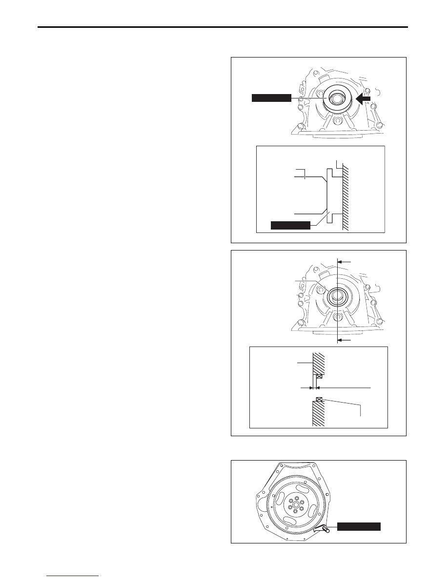
Front Oil Seal Assembly Note

1. Apply clean engine oil to the inner surface of a new front oil seal.

2. Insert the front oil seal into the engine front cover by hand.

3. Tap the oil seal in evenly using the 

SST and a 

hammer.

Front oil seal press on amount

0—0.5 mm {0—0.019 in}

Crankshaft Pulley Lock Bolt Assembly Note

1. Hold the crankshaft using the 

SST.

2. Tighten the crankshaft pulley lock bolt in the order 

shown in the following two steps.

Tightening procedure

Step 1: 90—110 N·m {9.2—11 kgf·m, 67—81 

ft·lbf}

Step 2: 55—65°

HAMMER

49 G028 205

ENGINE FRONT COVER

VIEW FROM A

A

49 G028 205

am3uuw00008830

FRONT OIL SEAL

0—0.5 mm 
{0—0.019 in}

ENGINE FRONT 
COVER

FRONT OIL SEAL

SECTION B-B

B

B

am3uuw00008831

49 E011 1A0

bpe1ze00000069

MECHANICAL 

01-10–81

01-10

Water Pump Pulley Assembly Note

Caution

• Be careful not to damage the belt groove and surface of the water pump pulley when using tools, 

otherwise it will cause wear, breakage, abnormal noise of the drive belt (stretch belt), damage to 

the pulley, and rust.

1. Install the water pump pulley to the water pump and temporarily tighten the bolt.

2. Align the water pump pulley hole with the water 

pump hole as shown in the figure.

3. Insert an appropriate bolt (length 

70 mm {2.8 in}

into the water pump hole shown in the figure and 

lock the water pump pulley against rotation.

4. Completely tighten the water pump pulley bolt to 

the specified torque.

Tightening torque

8—11 N·m {82—112 kgf·cm, 71—97 in·lbf}

5. Remove the bolt used for locking the water pump 

pulley against rotation.

Oil Shower Pipe Assembly Note

1. Install the oil shower pipe in the order shown in 

the figure.

WATER PUMP PULLEY

WATER PUMP

HOLE

HOLE

bpe2ue00000081

WATER PUMP PULLEY

BOLT

am3uuw00008874

2

3

2

3

1

1

OIL SHOWER 
PIPE

am3zzw00012759

MECHANICAL 

01-10–82

Tightening torque

Cylinder Head Cover Assembly Note

Caution

• To assure the sealing performance of the cylinder head cover, be careful of the following:

Verify that the cylinder head cover gasket is inserted into the cylinder head cover groove and 

install the cylinder head cover.

Completely clean and remove any oil, dirt, sealant or other foreign matter from the seal 

surface.

• To prevent silicone sealant from hardening, adhere the cylinder head cover and the cylinder head 

within 10 min. after silicone sealant is applied. Tighten the installation bolts completely soon after 

adhering.

1. Insert a new cylinder head cover gasket into the cylinder head cover groove.

Installation position

Tightening torque

1

9—12 N·m {92—122 kgf·cm, 80—106 in·lbf}

2, 3

8.0—9.0 N·m {82—91 kgf·cm, 71—79 in·lbf}

MECHANICAL 

01-10–83

01-10

2. Apply silicone sealant to the areas shown in the figure.

3. Tighten the cylinder head cover bolts in the order 

shown in the figure.

Tightening torque

4.5—7.0 N·m {46—71 kgf·cm, 40—61 in·lbf}

End Of Sie

SEALANT

SEALANT

ENGINE FRONT SIDE

ENGINE REAR SIDE

CYLINDER HEAD

CYLINDER HEAD

ENGINE FRONT COVER

ENGINE FRONT 
COVER MATCHING 
SURFACE

EXHAUST-SIDE REAR 
CAMSHAFT CAP

A

VIEW FROM A

CYLINDER 
HEAD

ENGINE 
FRONT 
COVER

B

VIEW FROM B

3—13 mm 
{0.2—0.5 in}

CYLINDER HEAD

EXHAUST-SIDE 
REAR CAMSHAFT 
CAP

3—13 mm 
{0.2—0.5 in}

2—6 mm 
{0.1—0.2 in}

2—6 mm 
{0.1—0.2 in}

2—6 mm 
{0.1—0.2 in}

2—6 mm 
{0.1—0.2 in}

2—6 mm 
{0.1—0.2 in}

SEALANT

SEALANT

4—5 mm 
{0.16—0.19 in}

4—5 mm 
{0.16—0.19 in}

SEALANT

SEALANT

4—5 mm 
{0.16—0.19 in}

bpe2ue00000082

3

8

7

4

9

6

2

5

1

15

12

10

14

13

11

am3uuw00008879


Content   ..  22  23  24  25   ..