Mazda engine MZR–CD. Manual - part 10
 

  Index      Mazda     Mazda engine MZR–CD - service manual 2002 year


Search            


Content   ..  8  9  10  11   ..


Mazda engine MZR–CD. Manual - part 10


B–20

ENGINE 

CYLINDER BLOCK INSPECTION/REPAIR

AME222410300102

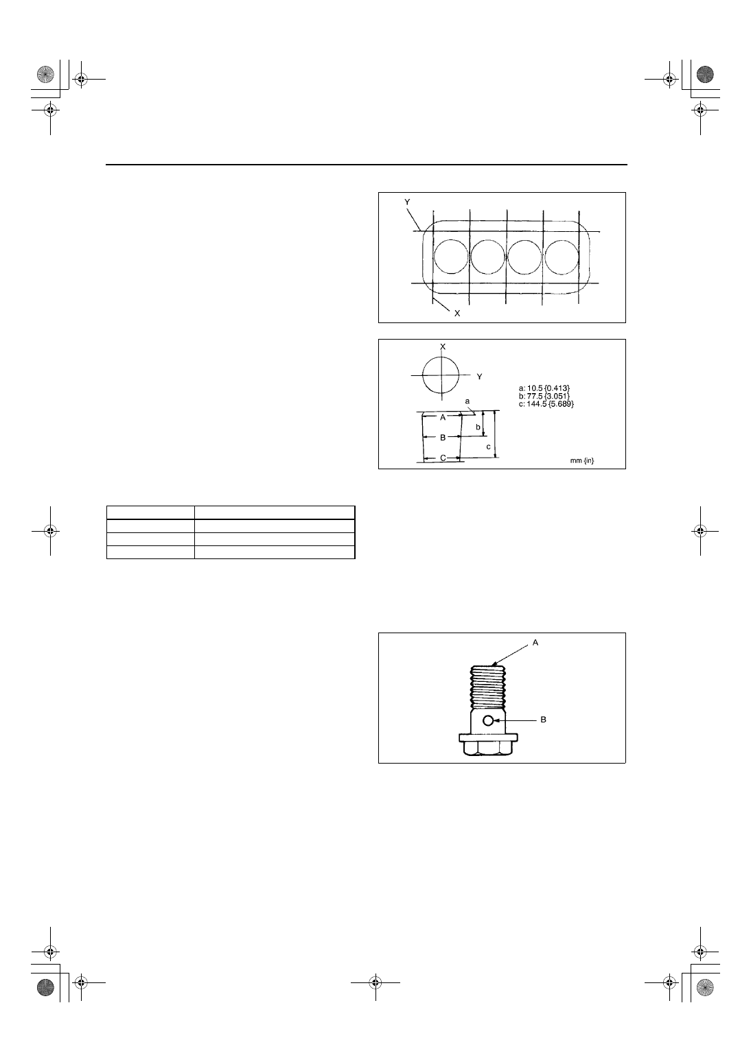
1. Measure the distortion of the cylinder block top 

surface in the seven directions as shown. 
Replace in necessary.

Maximum cylinder block distortion

X direction 0.01 mm {0.0004 in}
Y direction 0.03 mm {0.0012 in}

2. Measure the cylinder bores in X and Y directions 

at three levels (A,B and C) in each cylinder as 
shown.

3. If the cylinder bore exceeds the wear limit, 

replace the cylinder block or rebore the cylinder 
and install the oversize pistons so that the 
specified piston-to-cylinder clearance is obtained.

Note

Base the boring diameter on the diameter of 
an oversize piston. All cylinders must have 
the same diameter.

Cylinder bore

(mm {in})

Wear limit

0.15 mm {0.006 in}

End Of Sie

OIL JET VALVE, NOZZLE INSPECTION

AME222410730101

1. Apply compressed air to oil jet valve port A and 

verify that air passes through oil jet valve port B. If 
not, replace the oil jet valve.

Air pressure
138—196 kpa {1.4—2.0 kgf/cm

2

, 20—28 psi}

2. Inspect the oil jet nozzle for clogging. Replace the 

nozzle if necessary.

End Of Sie

Size

Diameter

Standard

86.000—86.022 {3.3859—3.3866}

0.25 {0.01} oversize

86.250—86.272 {3.3957—3.3965}

0.50 {0.02} oversize

86.500—86.522 {3.4055—3.4063}

AME2524E038

AME2524E040

AME2524E041

ENGINE 

B–21

B

PISTON INSPECTION

AME222411010102

Measure the outer diameter of each piston at right 
angle (90

°°°°

) to the piston pin, 10.0 mm {0.39 in} 

above the bottom of piston.

Piston diameter

mm {in}

End Of Sie

PISTON CLEARANCE INSPECTION/REPAIR

AME222411010103

1. Measure the piston-to-cylinder clearance. 

Replace the piston or rebore the cylinders to fit oversize piston if necessary.

Standard clearance

0—0.034 mm {0—0.0013 in}

Maximum clearance

0.10 mm {0.0039 in}

2. If the piston is replaced, the piston rings must also be replaced.

End Of Sie

PISTON RING CLEARANCE INSPECTION

AME222411010104

1. Measure the piston ring-to-ring gloove clearance 

around the entire circumference. Replace the 
piston and piston ring if necessary.

Standard clearance

Top: 0.05—0.09 mm {0.0020—0.0035 in}
Second: 0.04—0.08mm {0.0016—0.0031 in}
Oil: 0.03—0.07mm {0.0012—0.0027 in}

Maximum clearance

0.15 mm {0.0059 in}

2. Insert the piston ring into the cylinder by hand and 

use the piston to push it to the bottom of the ring 
travel.

3. Measure each piston ring end gap using a feeler 

gauge. Replace the piston ring if necessary.

Standard end gap

Top: 0.20—0.30 mm {0.008—0.011 in}
Second: 0.20—0.30 mm {0.008—0.011 in}
Oil rail: 0.20—0.30 mm {0.008—0.011 in}

Maximum end gap

1.0 mm {0.039 in}

End Of Sie

Size

Diameter

Standard

85.973—86.015 {3.3848—3.3864}

0.25 {0.01} oversize

86.223—86.265 {3.3946—3.3962}

0.50 {0.02} oversize

86.473—86.515 {3.4045—3.4061}

AME2524E042

AME2524E043

AMJ2224E104

B–22

ENGINE 

PISTON PIN CLEARANCE INSPECTION

AME222411010105

1. Measure each piston pin hole diameter in X and Y 

directions at the four points (A, B, C, and D) as 
shown.

Standard diameter

29.997—30.007 mm {1.1810—1.1813 in}

2. Measure each connecting rod small end inner 

diameter in X and Y directions as shown.

Standard diameter

30.014—30.030 mm {1.1817—1.1822 in}

3. Measure each piston pin diameter in X and Y 

directions at the four points (A, B, C, and D) as 
shown.

Standard diameter

29.994—30.000 mm {1.1809—1.1811 in}

4. Calculate the piston pin-to-piston pin bore 

clearance. Replace the piston or piston pin or 
both if necessary.

Standard clearance

- 0.003—0.013 mm {-0.00011—0.00051 in}

5. Calculate the clearance between connecting rod small end and piston pin. Replace the connecting rod or 

piston pin if necessary.

Standard clearance

 0.014—0.036 mm {0.00056—0.00141 in}

End Of Sie

CRANKSHAFT INSPECTION

AME222411301101

1. Measure the crankshaft runout. Replace the 

crankshaft if necessary.

Maximum runout

0.03 mm {0.001 in}

AME2524E044

AME2524E045

AME2524E046

AME2524E047

ENGINE 

B–23

B

2. Measure the journal diameter in X and Y direction 

at the two points (A and B) as shown. Replace the 
crankshaft or grind the journal, and install the 
undersize bearing if necessary.

Main Journal

(mm {in})

Out-of-round

0.03 mm {0.001 in} max.

Crank pin

(mm {in})

Out-of-round

0.03 mm {0.001 in} max.

End Of Sie

CRANKSHAFT OIL CLEARANCE INSPECTION/REPAIR

AME222411301102

1. Position a plastigage above the journals in the axial direction.
2. Install the main bearing cap. (See 

B–31 Main Bearing Cap Assembly Note

)

3. Remove the main bearing cap. (See 

B–14 Main Bearing Cap Disassembly Note

)

4. Measure the main journal oil clearance. If the 

clearance exceeds the maximum, replace the 
main bearing or grind the main journal, and install 
the undersize bearings so that the specified oil 
clearance is obtained.

Standard clearance

0.025—0.044 mm {0.0010—0.0017 in}

Maximum clearance

0.08 mm {0.003 in}

(mm {in})

End Of Sie

Bearing size

Diameter

Standard

59.937—59.955

{2.3598—2.3604}

0.25 {0.01} undersize

59.687—59.705

{2.3499—2.3505}

0.50 {0.02} undersize

59.437—59.455

{2.3401—2.3407}

0.75 {0.03} undersize

59.187—59.205

{2.3302—2.3309}

Bearing size

Diameter

Standard

50.940—50.955

{2.0056—2.0060}

0.25 {0.01} undersize

50.690—50.705 

{1.9957—1.9962}

0.50 {0.02} undersize

50.440—50.455

{1.9859—1.9864}

0.75 {0.03} undersize

50.190—50.205

{1.9760—1.9765}

AMJ2224E036

Bearing size

Bearing thickness

Standard

2.007—2.022

{0.0791—0.0796}

0.25 {0.01} oversize

2.129—2.139

{0.0839—0.0842}

0.50 {0.02} oversize

2.254—2.264

{0.0888—0.0891}

0.75 {0.03} oversize

2.379—2.389

{0.0937—0.0940}

AME2524E049


Content   ..  8  9  10  11   ..