Mazda Transaxle G35M–R. Manual - part 13
 

  Index      Mazda     Mazda Transaxle G35M–R - service manual 2002 year


Search            


Content   ..  11  12  13  14   ..


Mazda Transaxle G35M–R. Manual - part 13


MANUAL TRANSAXLE 

J–33

J

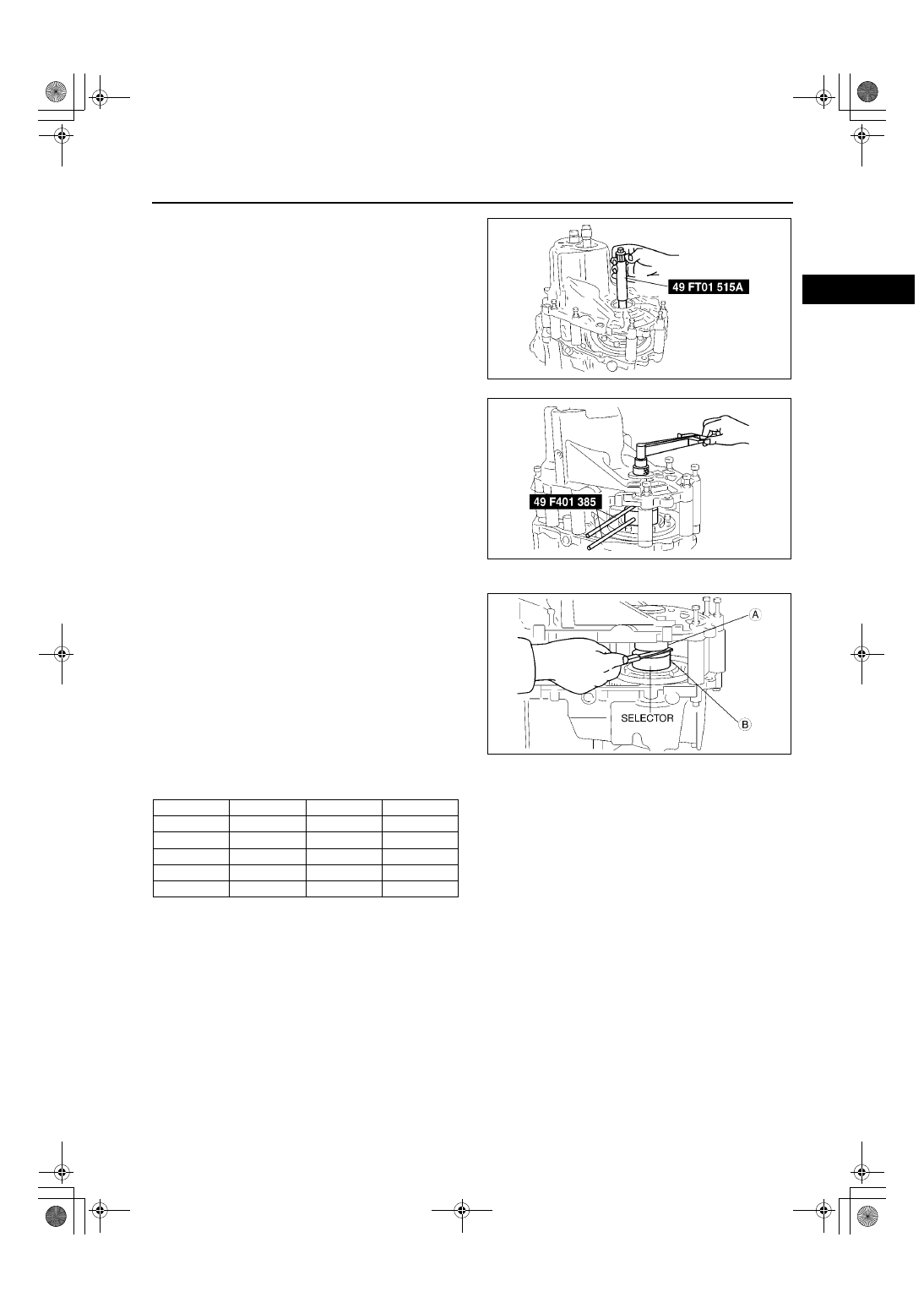
11. Install the SST and a pull scale or torque wrench.

12. Adjust the clearance of the SST (selector) to 

obtain the specified preload/pull scale reading.

Note

Read the preload when the differential starts 
to turn.

Measure several times and calculate the 
average value.

Preload

0.5 N·m {5.0 kgf·cm, 4.3 in·lbf}

Reading on pull scale

5 N {0.5 kgf, 1.1 lbf}

13. Use a feeler gauge to measure the gap in the 

selector for the differential.

14. Add 0.15 mm{0.006 in} to the measured 

clearance and select the combination of shims 
closest in value to that measurement.

Example

0.32 mm {0.013 in}

0.32 mm {0.013 in}+0.15 mm {0.006 

in}=0.47 mm {0.019 in}

Nearest shim (on thick side) to 0.47 mm 

{0.019 in} is 0.50 mm {0.020 in}

Thickness of shim

mm{in}

15. Remove the transaxle case and the SST.
16. Remove the selectors, the primary shaft component, and the differential.
17. Remove the bearing races.

0.1 {0.004}

0.20 {0.008}

0.25 {0.010}

0.30 {0.012}

0.35 {0.014}

0.40 {0.016}

0.45 {0.018}

0.50 {0.020}

0.55 {0.022}

0.60 {0.024}

0.65 {0.026}

0.70 {0.028}

0.75 {0.030}

0.80 {0.031}

0.85 {0.033}

0.90 {0.035}

0.95 {0.037}

1.0 {0.039}

1.05 {0.041}

1.10 {0.043}

1.15 {0.045}

1.20 {0.047}

Z4F5112M076

Z4F5112M077

Z4F5112M078

J–34

MANUAL TRANSAXLE 

18. Install the adjustment shim(s) and install the 

bearing race using a suitable pipe.

Caution

••••

Use the adjustment shim(s) selected 
during bearing preload adjustment.

19. Install the adjustment shim(s) and install the 

bearing race using a suitable pipe.

Caution

••••

Use the adjustment shim(s) selected 
during bearing preload adjustment.

20. Set the primary shaft gear component and the 

differential into the clutch housing.

21. Install the transaxle case, and tighten to the 

specified torque.

Tightening torque

37.3—52.0 N·m {3.8—5.3 kgf·m, 27.5—38.3 

ft·lbf}

22. Install the SST and a pull scale or torque wrench.
23. Verify that the preload is within the specification.

If not as specified, return to Step 1.

Preload

1.4—1.9 Nm {14—20 kgf·cm, 13—17 in·lbf}

Reading on pull scale

14—19 N {1.4—2.0 kgf, 3.1—4.4 lbf}

24. Remove the SST.

25. With the transaxle facing in the direction shown in 

the figure, install the SST to the primary shaft 
gear component.

26. Verify that the preload is within the specification.

If not as specified, return to Step 1.

Preload

0.12—0.39 N·m {1.2—4.0 kgf·cm, 1.05—3.47 

in·lbf}

Reading on pull scale

1.2—3.9 N {0.12—0.40 kgf, 0.27—0.88 lbf}

27. Remove the SST, transaxle case, primary shaft 

gear component and differential.

A6E5112M079

A6E5112M103

A6E5112M080

A6E5112M081

A6E5112M082

MANUAL TRANSAXLE 

J–35

J

28. Install the secondary shaft gear component and transaxle case, then tighten to the specified torque.

Tightening torque

37.3—52.0 N·m {3.8—5.3 kgf·m, 27.5—38.3 ft·lbf}

29. Install the SST and a pull scale or torque wrench.
30. Verify that the preload is within the specification.

If not as specification, return to Step 1.

Preload

0.2—0.3 N·m {2.0—4.0 kgf·cm, 1.8—3.4 

in·lbf}

Reading on pull scale

2—3 N {0.2—0.4 kgf, 0.5—0.8 lbf}

31. Remove the SST and transaxle case.

End Of Sie

Z4F5112M083

J–36

MANUAL TRANSAXLE 

CLUTCH HOUSING AND TRANSAXLE CASE COMPONENTS ASSEMBLY

A6E511217010M02

1. Assemble in the order shown in the figure..

A6E5112M112

1

Oil passage

2

Oil seal (differential)
(See 

J–37 Oil Seal (Differential) Assembly Note

)

3

Adjustment shim(s)

4

Bearing race (differential)
(See 

J–37 Bearing Race (Differential) Assembly 

Note

)

5

Adjustment shim(s)

6

Bearing race (transaxle case)
(See 

J–37 Bearing Race (Transaxle Case) 

Assembly Note

)

7

Drain plug and washer

8

Reverse lever

9

Reverse lever shaft

10

Bearing race (differential)
(See 

J–37 Bearing Race (Differential) Assembly 

Note

)

11

Oil seal (differential)
(See 

J–37 Oil Seal (Differential) Assembly Note

)

12

Hole cover

13

Bleather

14

Bleather cover component

15

Control rod

16

Selector

17

Roll pin

18

Change arm

19

Sealing cap

20

Guide plate component

21

Funnel

22

Bearing race (secondary shaft)

23

Oil seal (primary shaft)
(See 

J–38 Oil Seal (Primary Shaft)Assembly Note

)

24

Bearing race (primary shaft)

25

Boots 

26

Shift lever component

27

shift lever shaft

28

Key

29

Control end 

30

Spring and washer

31

Clank component lever


Content   ..  11  12  13  14   ..