Mazda CX-9 Grand Touring. Manual - part 487
 

  Index      Mazda     Mazda CX-9 Grand Touring - service repair manual 2008 year


Search            


Content   ..  485  486  487  488   ..


Mazda CX-9 Grand Touring. Manual - part 487


Fig. 50: DRL & Auto Light-Off System (Vehicles Without DRL) - Wiring Diagram 
Courtesy of MAZDA MOTORS CORP. 

AUTO LIGHT-OFF CONTROL MODULE 


2008 Mazda CX-9 Grand Touring 

2008 BODY & ACCESSORIES Lighting Systems - Mazda CX-9


Microsoft 


Sunday, November 15, 2009 10:39:06 AM

Page 29 

© 2005 Mitchell Repair Information Company, LLC. 

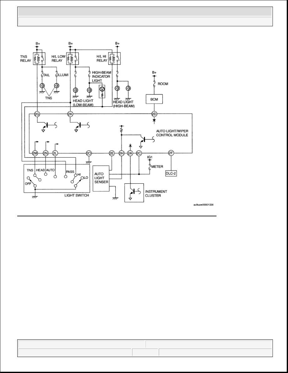
Fig. 51: DRL & Auto Light-Off System (Auto Light-Off Control Module) - Wiring Diagram 
Courtesy of MAZDA MOTORS CORP. 

AUTO LIGHT-OFF CONTROL MODULE REMOVAL/INSTALLATION 

1. Disconnect the negative battery cable.  

2. Remove the dashboard under cover (Driver side). (See DASHBOARD UNDER COVER 

REMOVAL/INSTALLATION .)  

3. Remove in the order indicated in the table. 


2008 Mazda CX-9 Grand Touring 

2008 BODY & ACCESSORIES Lighting Systems - Mazda CX-9


Microsoft 


Sunday, November 15, 2009 10:39:06 AM

Page 30 

© 2005 Mitchell Repair Information Company, LLC. 

Fig. 52: Identifying Auto Light-Off Control Module, Connector, Bolt & Torque Specifications 
Courtesy of MAZDA MOTORS CORP. 

4. Install in the reverse order of removal.  

AUTO LIGHT-OFF CONTROL MODULE INSPECTION 

1. Measure the voltage at the auto light-off control module terminals as indicated below.  

TERMINAL VOLTAGE LIST (REFERENCE) 

Fig. 53: Identifying Auto Light-Off Control Module Connector Terminals 
Courtesy of MAZDA MOTORS CORP. 

CONNECTOR TERMINALS REFERENCE 

Terminal

Signal

Connection

Test condition

Voltage 

Action


2008 Mazda CX-9 Grand Touring 

2008 BODY & ACCESSORIES Lighting Systems - Mazda CX-9


Microsoft 


Sunday, November 15, 2009 10:39:06 AM

Page 31 

© 2005 Mitchell Repair Information Company, LLC. 

AUTO LIGHT/WIPER CONTROL MODULE REMOVAL/INSTALLATION 

1. Disconnect the negative battery cable.  

2. Remove the dashboard under cover (Driver side). (See DASHBOARD UNDER COVER 

REMOVAL/INSTALLATION .)  

(V)

2C

IG 1

METER 10 A 
fuse

Ignition switch at ON

B+

METER 10 A fuse  

Related wiring harnesses 

Ignition switch at LOCK 
or ACC

1.0 or 
less

2D

Power 
supply

BCM  

ROOM 
15 A 
fuse  

Constant

B+

BCM (See BODY 
CONTROL MODULE 
(BCM) INSPECTION 
.) 

Inspect ROOM 15 A fuse 

Related wiring harnesses 

2G

TNS relay 
operation

TNS relay

Light switch at low-
beam or high-beam 
position

Below 

1.5

TAIL 10 A fuse  

TNS relay (See RELAY 
INSPECTION
 .)  

Related wiring harnesses 

Light switch at OFF

B+

2K

H/L LOW 
relay 
operation

H/L LOW 
relay

Light switch at high-
beam position

Below 

1.5

H/L LOW relay (See 
RELAY 
INSPECTION
 .)  

Related wiring harnesses 

Light switch at OFF or 
low-beam position

B+

2M

TNS switch 
on/off

Light switch

Ignition 
switch at 
ON

Light switch 
at low-beam 
or high-beam 
position

1.0 or 

less

Light switch (See 
LIGHT SWITCH 
INSPECTION
.)  

Related wiring harnesses 

Light switch 
at OFF 
position

B+

2N

Light 
switch 
on/off

Light switch

Ignition 
switch at 
ON

Light switch 
at low-beam 
or high-beam 
position

1.0 or 

less

Light switch (See 
LIGHT SWITCH 
INSPECTION
.)  

Related wiring harnesses 

Light switch 
at OFF 
position

B+

2O

GND

GND

Under any condition

1.0 or 

less

Related wiring harnesses 

NOTE:

Auto light-off system are integrated with the auto light/wiper control 
module.  


2008 Mazda CX-9 Grand Touring 

2008 BODY & ACCESSORIES Lighting Systems - Mazda CX-9


Microsoft 


Sunday, November 15, 2009 10:39:06 AM

Page 32 

© 2005 Mitchell Repair Information Company, LLC. 


Content   ..  485  486  487  488   ..