Mazda 6. Manual - part 359
 

  Index      Mazda     Mazda 6 - service repair manual 2002 year


Search            


Content   ..  357  358  359  360   ..


Mazda 6. Manual - part 359


ON-BOARD DIAGNOSTIC [CRUISE CONTROL SYSTEM] 

T–183

T

End Of Sie

DTC 35

A6E817266350W06

Diagnostic procedure

* 7

VERIFY WHICH IS MALFUNCTIONING‚ 
CRUISE ACTUATOR AND WIRING HARNESS 
(BRAKE SWITCH 2 AND CRUISE 
ACTUATOR) OR BRAKE SWITCH 2

• Disconnect brake switch connector.

• Turn ignition switch ON position.

• Is voltage at brake switch connector terminal 

approximately 12 V?

Yes

Go to next step.

No

Inspect brake switch 2.
(See 

P–8 BRAKE SWITCH INSPECTION

)

* 8

INSPECT WIRING HARNESS BETWEEN 
BRAKE SWITCH 2 AND CRUISE ACTUATOR 
FOR SHORT TO POWER SUPPLY

• Turn ignition switch to LOCK position.

• Disconnect cruise actuator connector.

• Turn ignition switch ON position.

• Is voltage at cruise actuator connector 

terminal K approximately 12 V?

Yes

Repair wiring harness. (Cruise actuator—Brake switch 2)

No

Repalce cruise actuator.
(See 

T–110 CRUISE ACTUATOR REMOVAL/

INSTALLATION

)

STEP

INSPECTION

ACTION

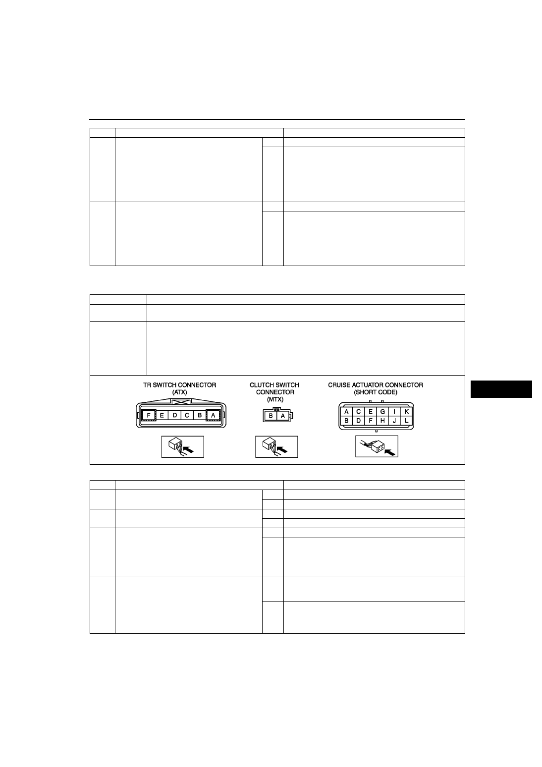
DTC 35

Clutch switch (MTX), TR switch (ATX)

DETECTION 

CONDITION

• Voltage detected at cruise actuator connector terminal F is not approximately 0 V.

POSSIBLE 

CAUSE

• Cruise actuator malfunction

• Starter relay malfunction (ATX)

• Clutch switch malfunction (MTX)

• TR switch malfunction (ATX)

• Open circuit in wiring harness between PCM and clutch switch (MTX)

• Open circuit in wiring harness between starter relay and TR switch (ATX)

• Open circuit in wiring harness between cruise actuator and clutch switch (MTX) or TR switch (ATX)

STEP

INSPECTION

ACTION

1

• Does vehicle has MTX?

Yes

Go to next step.

No

Go to step 5.

 2

INSPECT CLUTCH SWITCH 
Is clutch switch okay?

Yes

Go to next step.

No

Replace clutch switch.

* 3

INSPECT WIRING HARNESS BETWEEN 
CLUTCH SWITCH AND GROUND FOR 
CONTINUITY

• Disconnect clutch switch connector.

• Is there continuity between clutch switch 

connector terminal B and ground?

Yes

Go to next step.

No

Repair wiring harness. 
(Clutch switch—ground)

* 4

INSPECT WIRING HARNESS BETWEEN 
CRUISE ACTUATOR AND CLUTCH SWITCH 
FOR CONTINUITY

• Disconnect cruise actuator connector.

• Is there continuity between cruise actuator 

connector terminal F and clutch switch 
connector terminal A?

Yes

Replace cluise actuator.
(See

T–110 CRUISE ACTUATOR REMOVAL/

INSTALLATION

)

No

Repair wiring harness.
(Cruise actuator—clutch switch)

T–184

ON-BOARD DIAGNOSTIC [CRUISE CONTROL SYSTEM] 

End Of Sie

DTC 37

A6E817266350W07

Diagnostic procedure

5

INSPECT TR SWITCH

• Inspect TR switch.

(See 

K–14 TRANSAXLE RANGE (TR) SWITCH 

INSPECTION

)

• Is TR switch okay?

Yes

Go to next step.

No

Repair TR switch.
(See 

K–15 TRANSAXLE RANGE (TR) SWITCH REMOVAL/

INSTALLATION

)

* 6

INSPECT WIRING HARNESS BETWEEN TR 
SWITCH AND GROUND FOR CONTINUITY

• Disconnect TR switch connector.

• Is there continuity between TR switch 

connector terminal A and ground?

Yes

Go to next step.

No

Repair wiring harness (TR switch—ground ) or inspect 
starter.

* 7

INSPECT WIRING HARNESS BETWEEN 
CRUISE ACTUATOR AND TR SWITCH FOR 
CONTINUITY

• Disconnect cruise actuator connector.

• Is there continuity between cruise actuator 

connector terminal F and TR switch 
connector terminal F?

Yes

Replace cruise actuator.
(See

T–110 CRUISE ACTUATOR REMOVAL/

INSTALLATION

)

No

Repair wiring harness. (cruise actuator—TR switch)

STEP

INSPECTION

ACTION

DTC 37

Vehicle speed sensor

DETECTION 

CONDITION

• Vehicle speed signal is not detected at cruise actuator connector terminal A.

POSSIBLE

CAUSE

• Cruise actuator malfunction

• DSC HU/CM (with ABS/TCS HU/CM)

• Open or short circuit in wiring harness between ABS/TCS cruise actuator and DSC HU/CM (without 

DSC: ABS/TCS HU/CM)

STEP

INSPECTION

ACTION

1

INSPECT SPEEDOMETER OPERATION

• Does speedometer operate correctly?

Yes

Go to next step.

No

Perform instrument cluster input/output check 
mode.
(See 

T–75 INSTRUMENT CLUSTER INPUT/

OUTPUT CHECK MODE

)

2

INSPECT PCM ON-BOARD DIAGNOSTIC

• Drive the vehicle at more than 40 km/h {25 mph}.

• Check the DTC for PCM ON-BOARD 

DIAGNOSTIC.

• Is DTC P0500 displayed?

Yes

Go to applicable DTC inspection.

No

Go to next step.

* 3

VERIFY WHICH IS MALFUNCTIONING‚ WIRING 
HARNESS WITH DSC OR CRUISE ACTUATOR 

• Disconnect cruise actuator connector and DSC 

HU/CM connector.

• Is there continuity between cruise actuator 

connector terminal A and DSC HU/CM connector 
terminal AE?

With ABS/TCS

• Disconnect cruise actuator connector and ABS/

TCS HU/CM connector.

• Is there continuity between cruise actuator 

connector terminal A and ABS/TCS connector 
terminal V?

Yes

Replace cruise actuator.
(See 

T–110 CRUISE ACTUATOR REMOVAL/

INSTALLATION

)

No

Repair wiring harness.
With DSC
(DSC HU/CM—Cruise actuator)
With ABS/TCS
(ABS/TCS HU/CM—Cruise actuator)

ON-BOARD DIAGNOSTIC [CRUISE CONTROL SYSTEM] 

T–185

T

End Of Sie

INSPECTION OF DTCS FOR CONDITION DETECTION MODE

A6E817266350W08

Note

• The cruise set indicator light will illuminate for 3 seconds, when condition detection mode is on.

• If the RESUME/ACCEL switch on the cruise control switch is malfunctioning, the cruise set indicator light 

will not give a correct indication when you inspect the system.

1. Drive the vehicle at 30 km/h {19 mph} or more.
2. Press on the cruise control main switch (1).
3. Operate each of the cruise control switches.
4. Stop the vehicle and let it idle.
5. Turn and hold the RESUME/ACCEL switch on for 

at least 3 seconds (2). The cruise set indicator 
light will illuminate for 3 seconds, and then go off 
for at least 2 seconds. Thus, the condition 
detection mode begins.

• If a DTC is indicated, inspect the 

corresponding system area.

• If normal, DTC(s) will not be indicated.

6. The condition detection mode is canceled by 

turning the ignition switch to LOCK position or 
turning off the cruise control main switch.

Condition Code List

Note

• When two or more DTCs are indicated, inspect the malfunction with the smallest number first.

Inspection of Diagnostic Trouble Codes
Foreword

• When performing an asterisked (*) troubleshooting inspection‚ shake the wiring harness and connectors while 

doing the inspection to discover whether poor contact points are the cause of any intermittent malfunction. If 
there is a problem‚ check to make sure connectors‚ terminals and wiring harness are connected correctly and 
undamaged.

End Of Sie

A6E8172W013

DTC

Output pattern

Diagnosed circuit

Page

01

Cruise actuator (Drive circuit)

(See 

T–186 DTC 01

)

05

Brake switch

(See 

T–186 DTC 05

)

07

Brake switch
Brake switch 2

(See 

T–186 DTC 07

)

11

Cruise control switch (SET/
COAST switch)

(See 

T–187 DTC 11

)

12

Cruise control switch (RESUME/
ACCEL switch)

(See 

T–187 DTC 12

)

13

Cruise control switch (Ground 
circuit)

(See 

T–188 DTC 13

)

15

Cruise actuator (Control circuit)

(See 

T–188 DTC 15

)

T–186

ON-BOARD DIAGNOSTIC [CRUISE CONTROL SYSTEM] 

DTC 01

A6E817266350W09

Diagnostic procedure

End Of Sie

DTC 05

A6E817266350W10

Diagnostic procedure

End Of Sie

DTC 07

A6E817266350W11

DTC 01

Cruise actuator (Drive circuit)

DETECTION 

CONDITION

• Malfunction in cruise actuator circuit (drive circuit)

POSSIBLE 

CAUSE

• Cruise actuator malfunction

ACTION

REPLACE CRUISE ACTUATOR IF IT IS MALFUNCTIONING

• Replace cruise actuator.

(See 

T–110 CRUISE ACTUATOR REMOVAL/INSTALLATION

)

DTC 05

Brake switch

DETECTION 

CONDITION

• Voltage detected at cruise actuator connector terminal C is always approximately 0 V.

POSSIBLE 

CAUSE

• Cruise actuator malfunction

INSPECTION

ACTION

INSPECT DTC FOR OPERATION MODE

• Was operation mode for DTC 31 performed?

Yes

Perform operation mode for DTC 31 on-board diagnostic 
again. Even if no malfunction is detected in operation mode, 
if DTC 05 is indicated in condition detection mode on-board 
diagnostic, replace cruise actuator.
(See 

T–110 CRUISE ACTUATOR REMOVAL/

INSTALLATION

)

No

Perform operation mode for DTC 31.

DTC 07

Brake switch
Brake switch 2

DETECTION 

CONDITION

• Voltage detected at cruise actuator connector terminal C or K is always approximately 12 V.

• Voltage detected at cruise actuator connector terminal K is always approximately 0 V.

POSSIBLE 

CAUSE

• METER IG15 A fuse burnt out

• Brake switch and/or brake switch 2 malfunction

• Cruise actuator malfunction

• Open circuit in wiring harness between STOP 15 A fuse and brake switch

• Open or short circuit in wiring harness between brake switch and cruise actuator terminal C

• Open circuit in wiring harness between brake switch 2 and METER IG15 A fuse

• Open or short circuit in wiring harness between cruise actuator terminal K and brake switch 2


Content   ..  357  358  359  360   ..