Mazda 6. Manual - part 322
 

  Index      Mazda     Mazda 6 - service repair manual 2002 year


Search            


Content   ..  320  321  322  323   ..


Mazda 6. Manual - part 322


T–48

INTERIOR LIGHTING SYSTEM 

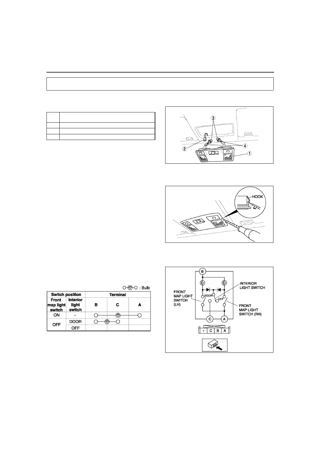
FRONT MAP LIGHT REMOVAL/INSTALLATION

A6E811451310W01

1. Disconnect the negative battery cable.
2. Remove in the order indicated in the table.

3. Install in the reverse order of removal.

Front Map Light Removal Note

1. Insert a tape-wrapped flathead screwdriver into the gap between the headliner and the front map light.
2. Push the hooks to remove the front map light.

End Of Sie

FRONT MAP LIGHT INSPECTION

A6E811451310W02

1. Remove the front map light. (See 

T–48 FRONT MAP LIGHT REMOVAL/INSTALLATION

.)

2. Inspect for continuity between the front map light 

terminals using an ohmmeter.

• If not as specified, replace the front map light.

End Of Sie

INTERIOR LIGHTING SYSTEM

1

Front map light (See 

T–48 Front Map Light Removal 

Note

)

2

Connector

3

Socket

4

Map light bulb

A6E8114W102

A6E8114W103

A6E8114W118

A6E8114W117

INTERIOR LIGHTING SYSTEM 

T–49

T

REAR MAP LIGHT REMOVAL/INSTALLATION

A6E811451311W01

1. Disconnect the negative battery cable.
2. Remove in the order indicated in the table.

3. Install in the reverse order of removal.

Rear Map Light Removal Note

1. Insert a tape-wrapped flathead screwdriver into the gap between the headliner and the rear map light.
2. Push the hooks to remove the rear map light.

End Of Sie

REAR MAP LIGHT INSPECTION

A6E811451311W02

1. Remove the rear map light. (See 

T–49 REAR MAP LIGHT REMOVAL/INSTALLATION

.)

2. Inspect for continuity between the rear map light 

terminals using an ohmmeter.

• If not as specified, replace the rear map light.

End Of Sie

1

Rear map light (See 

T–49 Rear Map Light Removal 

Note

)

2

Connector

3

Socket

4

Rear map light bulb

A6E8114W104

A6E8114W105

A6E8114W128

A6E8114W127

T–50

INTERIOR LIGHTING SYSTEM 

CARGO COMPARTMENT LIGHT REMOVAL/INSTALLATION

A6E811451441W01

1. Disconnect the negative battery cable.
2. Remove in the order indicated in the table.

3. Install in the reverse order of removal.

End Of Sie

CARGO COMPARTMENT LIGHT INSPECTION

A6E811451441W02

1. Remove the cargo compartment light. (See 

T–50 CARGO COMPARTMENT LIGHT REMOVAL/

INSTALLATION

)

2. Inspect for continuity between the cargo 

compartment light terminals using an ohmmeter.

• If not as specified, replace the cargo 

compartment light.

End Of Sie

CARGO COMPARTMENT LIGHT SWITCH INSPECTION

A6E811451442W01

1. Remove the liftgate lower trim. (See 

S–95 LIFTGATE LOWER TRIM REMOVAL/INSTALLATION

)

2. Disconnect the cargo compartment light switch connector.
3. Inspect for continuity between the cargo 

compartment light switch terminals using an 
ohmmeter.

• If not as specified, replace the liftgate lock.

End Of Sie

1

Cargo compartment light

2

Connector

3

Lens

4

Cargo compartment light bulb

A6E8114W101

A6E8114W111

A6E8114W114

A6E8114W119

A6E8114W120

INTERIOR LIGHTING SYSTEM 

T–51

T

TRUNK COMPARTMENT LIGHT BULB REMOVAL/INSTALLATION

A6E811451440W01

1. Disconnect the negative battery cable.
2. Remove in the order indicated in the table.

3. Install in the reverse order of removal.

End Of Sie

TRUNK COMPARTMENT LIGHT SWITCH INSPECTION

A6E811451440W02

1. Remove the trunk lid trim. (See 

S–93 TRUNK LID TRIM REMOVAL/INSTALLATION

)

2. Disconnect the trunk compartment light switch connector.
3. Inspect for continuity between the trunk 

compartment light switch terminals using an 
ohmmeter.

• If not as specified, replace the trunk lock.

End Of Sie

COURTESY LIGHT BULB REMOVAL/INSTALLATION

A6E811469971W01

1. Disconnect the negative battery cable.
2. Remove in the order indicated in the table.

3. Install in the reverse order of removal.

End Of Sie

1

Lens 

2

Trunk compartment light bulb

A6E8114W112

A6E8114W119

A6E8114W121

1

Lens

2

Courtesy light bulb

A6E8114W110


Content   ..  320  321  322  323   ..