Mazda 6. Manual - part 264
P–112
TROUBLESHOOTING (ABS/TCS/DYNAMIC STABILITY CONTROL)
4
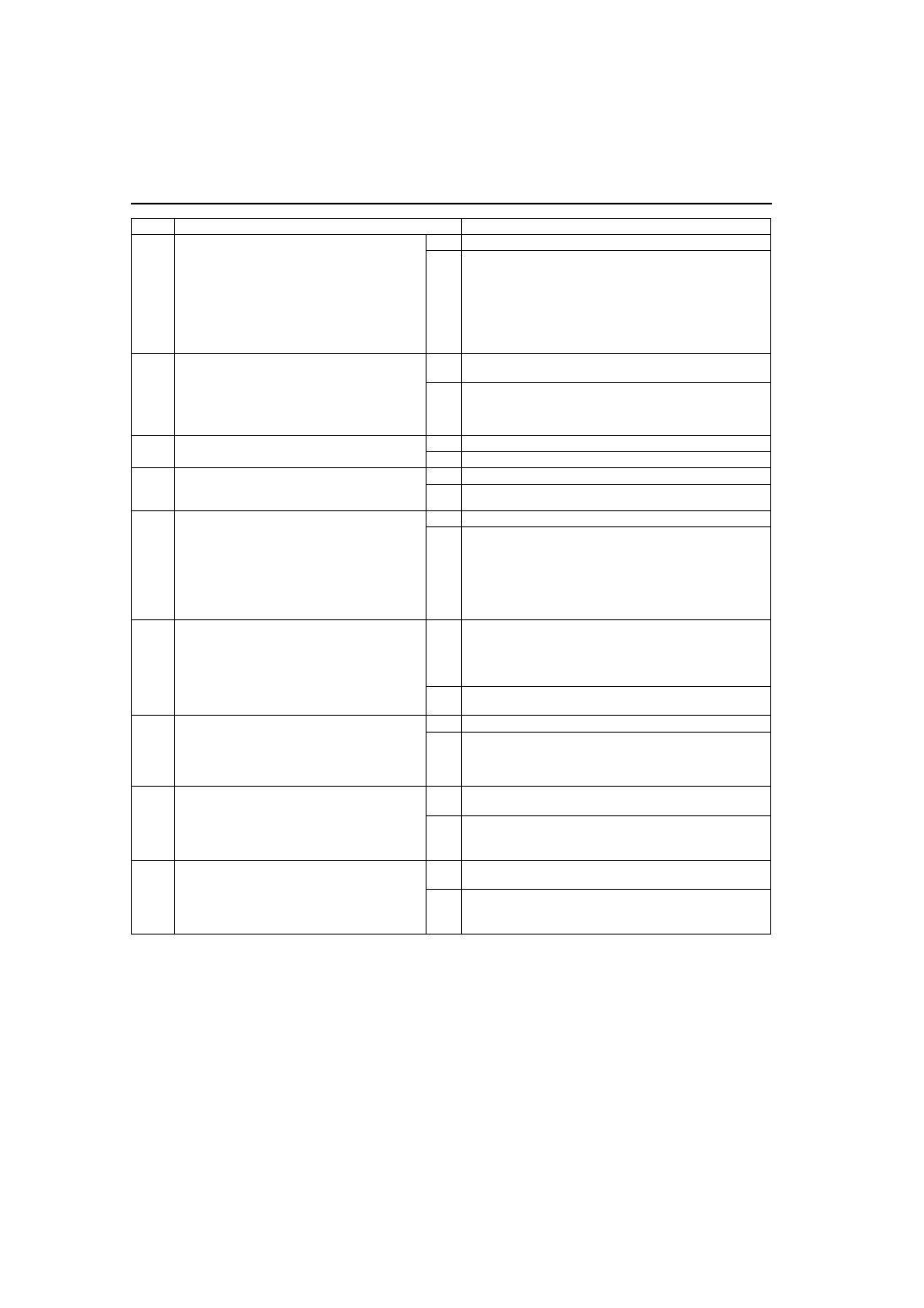
INSPECT PID/DATA IN ABS/TCS HU/CM
Inspect the following items using WDS or
equivalent PID/DATA monitor function.
• ABS_LAMP (ABS warning light)
• BRAKE_ LAMP (BRAKE system warning
light)
• ABS_VOLT (power supply voltage)
Is ABS_LAMP and BRAKE_LAMP ON after
more than 4 seconds with ignition switch on?
Yes
Go to Step 7.
No
Go to next step.
5
INSPECT ABS/TCS HU/CM IGNITION POWER
SUPPLY SYSTEM (TERMINAL Z)
Check the voltage for PID/DATA monitor
ABS_VOLT item.
Specification: about 10 V
Is voltage within specification?
Yes
Replace ABS/TCS HU/CM (open or short in ground circuit in
ABS/TCS HU/CM)
No
Go to next step.
6
INSPECT BATTERY
Is battery voltage normal?
Yes
Go to next step.
No
Inspect battery and charging system.
7
INSPECT CHARGING SYSTEM
Is battery voltage normal with electrical load (A/
C, headlight, etc.) on and engine idling?
Yes
Go to Step 7.
No
Inspect charging system (drive belt tension, generator, etc.).
*
8
INSPECT WIRING HARNESS BETWEEN ABS/
TCS HU/CM POWER SUPPLY AND ABS/TCS
HU/CM FOR CONTINUITY
Disconnect ABS/TCS HU/CM connector.
Connect the SST (49 G066 001) (vehicle
harness side only).
Is voltage approximately 12 V at SST
connector terminal Z?
Yes
Go to next step.
No
Check for connection of ABS/TCS HU/CM connector
securely.
*
9
INSPECT WIRING HARNESS BETWEEN ABS/
TCS HU/CM GROUND FOR CONTINUITY
Turn ignition switch to LOCK.
Is there continuity between SST connector
terminal AC and ground?
Yes
If a malfunction error message is displayed on WDS or
equivalent in Step 1 inspection, go to next step.
If a malfunction error message is not displayed on WDS or
equivalent in Step 1 inspection, troubleshooting is
completed.
No
Repair wiring harness between ABS/TCS HU/CM and
ground.
*
10
INSPECT WIRING HARNESS BETWEEN ABS/
TCS HU/CM AND DLC-2 (DATA LINK
CONNECTOR-2) FOR CONTINUITY
Is there continuity between SST connector
terminal X and DLC-2?
Yes
Go to next step.
No
Repair wiring harness between ABS/TCS HU/CM and
DLC-2.
11
*
INSPECT WIRING HARNESS BETWEEN
ABS/TCS HU/CM AND DLC-2 (DATA LINK
CONNECTOR-2) FOR SHORT TO BATTERY
Is voltage approximately 12 V at SST
connector terminal X?
Yes
Repair wiring harness between ABS/TCS HU/CM and
DLC-2.
No
Go to next step.
12
*
INSPECT WIRING HARNESS BETWEEN
ABS/TCS HU/CM AND DLC-2 (DATA LINK
CONNECTOR-2) FOR SHORT TO GROUND
Is there continuity between SST connector
Terminal X and DLC-2?
Yes
Repair wiring harness between ABS/TCS HU/CM and
DLC-2.
No
Replace ABS/TCS HU/CM (communication circuit
malfunction in ABS/TCS HU/CM)
STEP
INSPECTION
ACTION