Mazda 6. Manual - part 238
 

  Index      Mazda     Mazda 6 - service repair manual 2002 year


Search            


Content   ..  236  237  238  239   ..


Mazda 6. Manual - part 238


P–10

CONVENTIONAL BRAKE SYSTEM 

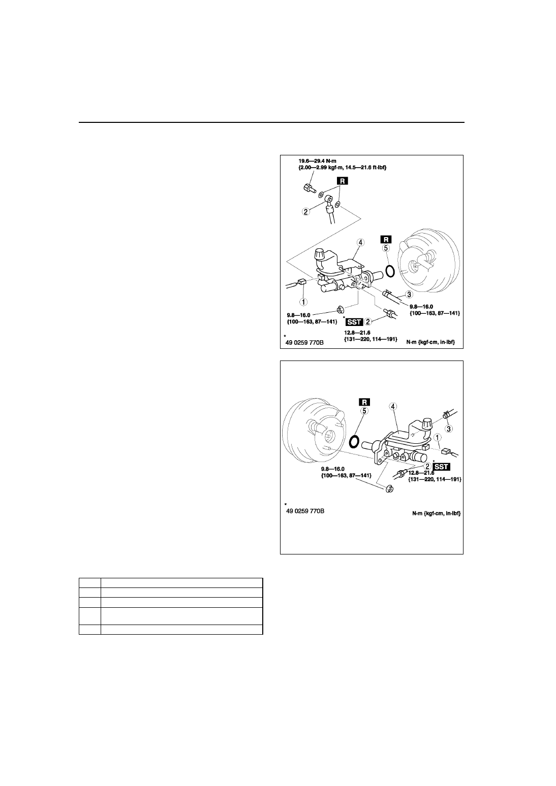
MASTER CYLINDER REMOVAL/INSTALLATION

A6E691243400W01

1. Remove in the order indicated in the table.

R.H.D.

L.H.D.

2. Install in the reverse order of removal.

A6E6912W028

A6E6912W018

1

Brake fluid level sensor connector

2

Brake pipe

3

Hose  (MTX)

4

Master cylinder
(See 

P–11 Master Cylinder Installation Note

5

O-ring

CONVENTIONAL BRAKE SYSTEM 

P–11

P

Master Cylinder Installation Note

Caution

• Always install the gasket of the power brake unit push rod before performing measurement 

inspections or adjustments.

1. Install the SST to the power brake unit as shown, 

and tighten within the specified torque.

Tightening torque

9.8—16.0 N·m {100—163 kgf·cm, 87—141 

in·lbf}

2. Using a vacuum gauge, create a vacuum 

pressure of 66.7 kPa {500 mmHg, 19.7 inHg} in 
the power brake unit.

3. Using calipers, measure dimension L as shown.

Specification

22.7 mm{8.94 in}

4. If dimension L is not within the specification as 

shown, remove SST (49 E043 001) and use SST 
(49 B043 004) to adjust the length of the push rod 
while using SST (E043 003A) to keep the push 
rod from rotating.

5. Remove the SSTs, replace SST (49 E043 001) 

and measure dimension L again.

A6E6912W042

A6E6912W029

A6E6912W030

A6E6912W031

P–12

CONVENTIONAL BRAKE SYSTEM 

6. Install the master cylinder to the power brake unit.

Caution

• If after installing the master cylinder, air 

does not bleed properly from the brake 
lines even after performing air bleeding, 
brake drag occurs or other 
characteristics are present, it is possible 
that the master cylinder piston is jammed 
against the power brake unit. If air cannot 
be bled properly, brake drag exists or 
other malfunctions occur, remove the 
master cylinder and reinstall properly.

End Of Sie

FLUID LEVEL SENSOR INSPECTION

A6E691243540W01

1. Disconnect the negative battery cable.
2. Disconnect the sensor connector.
3. Inspect for continuity between terminals of fluid level sensor.

• If not as specified, replace the fluid level sensor.

End Of Sie

MASTER CYLINDER DISASSEMBLY/ASSEMBLY

A6E691243400W02

Caution

• If the master cylinder body is damaged, replace the unit as a component. When securing the 

master cylinder in a vise, tighten only the flange of the master cylinder.

1. Disassemble in the order indicated in the table.
2. Assemble in the reverse order of disassembly.

.

A6E6912W032

A6E6912W024

A6E6912W023

A6E6912W019

1

Cap set

2

Screw

CONVENTIONAL BRAKE SYSTEM 

P–13

P

Stop Screw and O-ring (without ABS) Assembly Note

1. Install the secondary piston and primary piston.
2. Install the new O-ring onto the stop screw.
3. Push the primary piston assembly in full.
4. Install and tighten the stop screw.

Tightening torque

2.0—2.4 N·m {21—24 kgf·cm, 18—21 in·lbf}

5. Push and release the secondary piston 

component to verify that it is held properly by the 
stop screw.

Stop Pin and O-ring (with ABS) Assembly Note

1. Install the secondary piston with the piston hole facing the stop pin and primary piston.
2. Install the new O-ring onto the stop pin.
3. Push the primary piston assembly in full.
4. Install and tighten the stop pin.

Tightening torque

6.9—9.8 N·m {71—99 kgf·cm, 62—86 in·lbf}

5. Push and release the secondary piston 

component to verify that it is held properly by the 
stop pin.

End Of Sie

3

Reservoir

4

Joint bushing

5

Snap ring

6

Piston guide

7

Cup

8

Stopper

9

Primary piston

10

Stop pin and O-ring (with ABS)
(See 

P–13 Stop Pin and O-ring (with ABS) 

Assembly Note

)

11

Stop screw and O-ring (without ABS)
(See

P–13 Stop Screw and O-ring (without ABS) 

Assembly Note

)

12

Secondary piston

13

Master cylinder body

A6E6912W025

A6E6912W043


Content   ..  236  237  238  239   ..