Mazda 6. Manual - part 206
ON-BOARD DIAGNOSTIC
K–65
K
End Of Sie
DTC P0713
A6E567001030W11
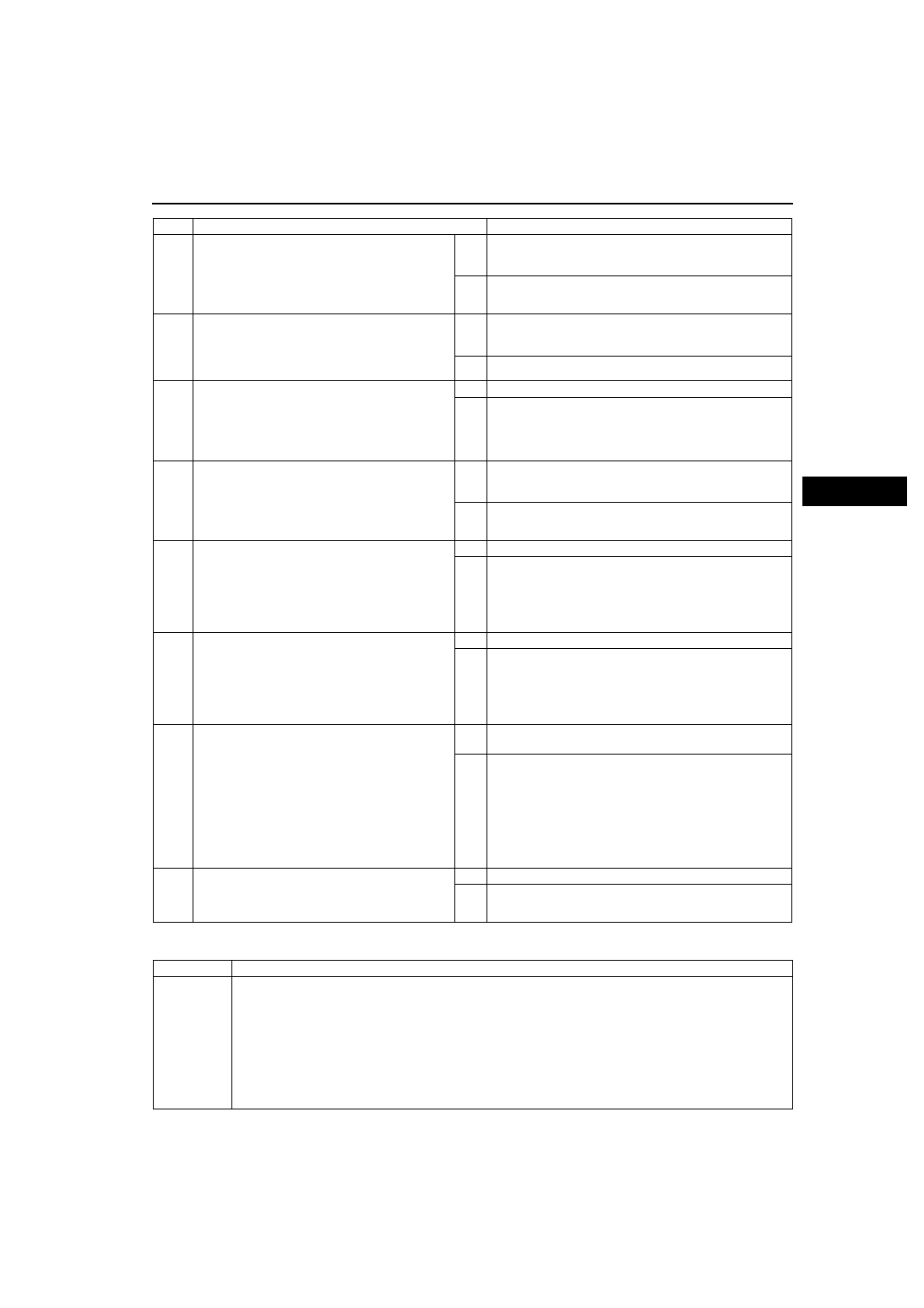
3
VERIFY CURRENT INPUT SIGNAL STATUS
• Turn ignition key to OFF.
• Connect breakout box to PCM.
• Turn ignition key to ON (engine OFF).
• Measure the voltage at PCM terminal 3D.
• Are voltage readings above 0.06 V?
Yes Go to intermittent concern troubleshooting procedure.
(See
No
Go to next step.
4
INSPECT TERMINAL CONDITION
• Turn ignition key to OFF.
• Disconnect ATX connector.
• Inspect for bent terminals.
• Are the terminals bent?
Yes Repair or replace terminals, then go to Step 9.
• If terminals cannot be repaired, replace harness, then
go to Step 9.
No
Go to next step.
5
INSPECT TFT SENSOR CIRCUIT
• Turn ignition key to ON (engine OFF).
• Verify if voltage changes to 4.67 V or above at
PCM terminal 3D when ATX connector
disconnected.
• Does voltage change?
Yes Go to next step.
No
Go to Step 8.
6
INSPECT TFT SENSOR TERMINALS
CONDITION
• Turn ignition key to OFF.
• Disconnect TFT sensor connector.
• Inspect for bent TFT sensor terminals.
• Are the terminals bent?
Yes Repair terminals or replace TFT sensor, then go to Step 9.
(See
K–21 TRANSAXLE FLUID TEMPERATURE (TFT)
.)
No
Go to next step.
7
INSPECT TFT SENSOR CIRCUIT FOR SHORT
TO GROUND
• Inspect for continuity between TFT sensor
terminals (harness-side) and body ground.
— A and body ground
— B and body ground
• Is there continuity?
Yes Repair or replace harness, then go to Step 9.
No
Replace TFT sensor, then go to step 9.
(See
K–21 TRANSAXLE FLUID TEMPERATURE (TFT)
.)
8
INSPECT ATX CONNECTOR CIRCUIT FOR
SHORT TO GROUND
• Turn ignition key to OFF.
• Inspect for continuity between ATX connector
terminal E (vehicle harness-side) and body
ground.
• Is there continuity?
Yes Repair or replace harness, then go to next step.
No
Go to next step.
9
VERIFY TROUBLESHOOTING OF DTC P0712
COMPLETED
• Make sure to reconnect all disconnected
connectors.
• Clear DTC from memory using WDS or
equivalent.
• Drive vehicle under following condition for 150
seconds or more.
— Vehicle speed (VSS PID) 20 km/h {12 mph}
or above.
• Is same DTC present?
Yes Replace PCM, then go to next step.
(See
No
Go to next step.
10
VERIFY AFTER REPAIR PROCEDURE
• Perform “After Repair Procedure”.
• Are any DTCs present?
Yes Go to applicable DTC inspection.
No
Troubleshooting completed.
STEP
INSPECTION
ACTION
DTC P0713
Transaxle fluid temperature (TFT) sensor circuit malfunction (open circuit)
DETECTION
CONDITION
• If PCM detects either of following conditions for 150 seconds or more, PCM determines that TFT sensor
circuit has a malfunction.
— TFT sensor voltage is 4.67 V or above and vehicle speed 20 km/h {12 mph} or above.
Diagnostic support note:
• This is a continuous monitor (CCM).
• MIL illuminates if PCM detects the above malfunction conditions during first drive cycle.
• PENDING CODE is not available.
• FREEZE FRAME DATA is available.
• HOLD indicator light flashes.
• DTC is stored in the PCM memory.