Mazda 6. Manual - part 195
 

  Index      Mazda     Mazda 6 - service repair manual 2002 year


Search            


Content   ..  193  194  195  196   ..


Mazda 6. Manual - part 195


AUTOMATIC TRANSAXLE 

K–25

K

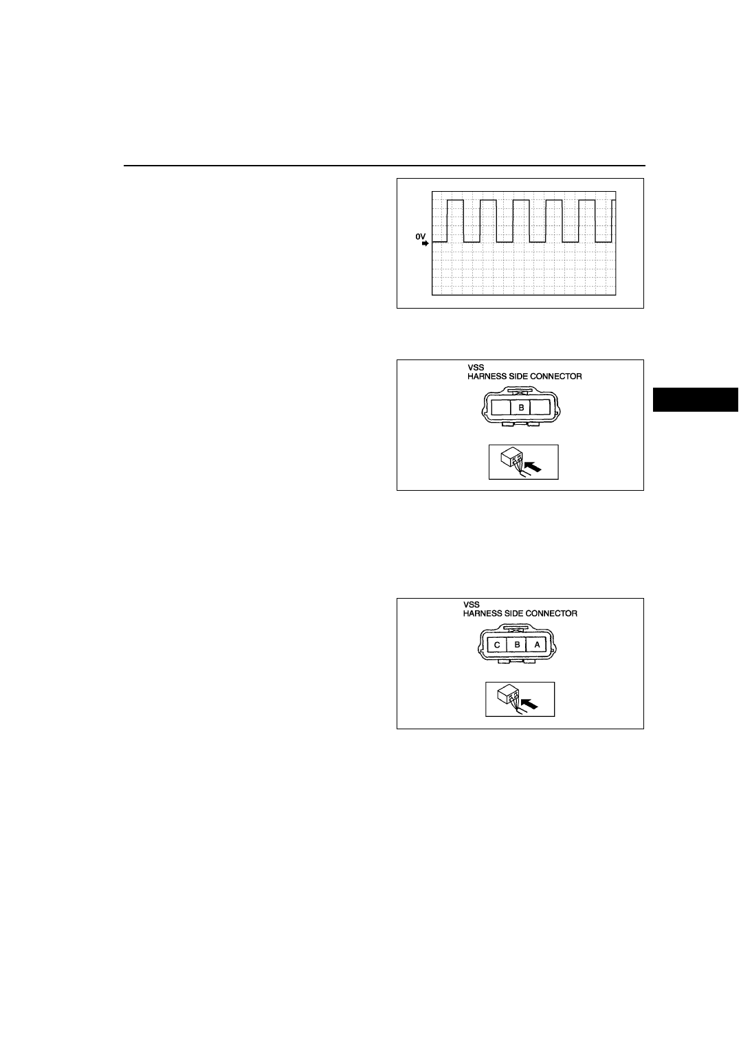
6. Inspect wave profile.

• PCM terminal: 3C (+) - 1D (-)

• Oscilloscope setting: 1 V/DIV (Y), 2.5 ms/DIV 

(X), DC range

• Vehicle condition: drive the vehicle with 32 

km/h{20 mph}
— If wave profile or voltage are out of 

specifications, carry out the “Open Circuit 
Inspection” or “Short Circuit Inspection”

Power Supply Voltage Inspection

1. Disconnect the VSS connector.
2. Turn the ignition switch to ON.
3. Measure voltage at VSS connector terminal B 

(wiring harness side).

Specification

4.5—5.5 V

• If voltage is okay, go to Open Circuit 

Inspection and Short Circuit Inspection.

• If voltage is wrong, repair wiring harness 

between VSS and PCM.

Open Circuit Inspection

1. Inspect the following circuit for open.

• Power circuit (VSS connector terminal A to main relay terminal D)

• Ground circuit (VSS connector terminal C to GND)

• If an open circuit or short circuit is found, repair the malfunctioning wiring harness.

• If there are no open or short circuits, perform the sensor rotor inspection. 

Short Circuit Inspection

1. Inspect the following circuit for short.

• Power circuit (VSS connector terminal A to 

main relay terminal D)

• If an open circuit or short circuit is found, 

repair the malfunctioning wiring harness.

• If there are no open or short circuits, perform 

the sensor rotor inspection. 

Sensor Rotor Inspection

1. Remove the VSS. (See 

K–26 VEHICLE SPEEDOMETER SENSOR (VSS) REMOVAL/INSTALLATION

.)

2. Shift the selector lever to N position.
3. Inspect sensor rotor surface via VSS installation hole while rotating the front tire manually.

(1) Is sensor rotor free of damage and cracks?
(2) Is sensor rotor free of any metallic shavings or particles?

• If sensor rotor is okay, replace the VSS.

• If there is a problem, clean or replace the sensor rotor.

End Of Sie

A6E5614W102

A6E5614W033

A6E5614W035

K–26

AUTOMATIC TRANSAXLE 

VEHICLE SPEEDOMETER SENSOR (VSS) REMOVAL/INSTALLATION

A6E561401030W06

Caution

• Water or foreign objects entering the connector can cause a poor connection or corrosion. Be 

sure not to drop water or foreign objects on the connector when disconnecting it.

• If foreign materials are stuck to the VSS, disturbance by magnetic flux can cause sensor output to 

be abnormal and thereby negatively affect control. Make sure that foreign materials such as iron 
filings are not stuck to the VSS during installation.

1. Disconnect the negative battery cable.
2. Remove the under cover.
3. Disconnect the VSS connector.
4. Remove the VSS.
5. Apply ATF to a new O-ring and install it on a new 

VSS.

6. Install the VSS.

Tightening torque

8—11 N·m {82—112 kgf·cm, 71—97 in·lbf}

7. Connect the VSS connector.
8. Install the under cover.
9. Connect the negative battery cable.

End Of Sie

SOLENOID VALVE INSPECTION

A6E561421280W01

Resistance Inspection (On-Vehicle Inspection)

Caution

• Water or foreign objects entering the connector can cause a poor connection or corrosion. Be 

sure not to drop water or foreign objects on the connector when disconnecting it.

1. Disconnect the negative battery cable.
2. Remove the air cleaner component. (See 

F–10 INTAKE-AIR SYSTEM REMOVAL/INSTALLATION

.)

3. Disconnect the transaxle connector.

Note

• When inspecting the pressure control 

solenoid, connect the ground connection to 
the ground terminal (terminal I) of the 
pressure control solenoid inside the solenoid 
valve connector.

A6E5614W037

A6E5614W037

A6E5614W021

AUTOMATIC TRANSAXLE 

K–27

K

4. Measure the resistance between the following 

terminals.

• If not as specified, inspect the ground, then 

perform the operating inspection.

ATF temperature: –40—150 

°C {–40—302 °F}

5. Connect the transaxle connector.
6. Install the air cleaner component. (See 

F–10 INTAKE-AIR SYSTEM REMOVAL/INSTALLATION

.)

7. Connect the negative battery cable.

Operating Inspection

1. Disconnect the transaxle connector.

Caution

• Do not apply battery position voltage to terminals A, B, C, D, F and G for more than three seconds.

Note

• Because the operation sound of the valves is small, perform inspection in a quiet place.

2. Apply battery positive voltage to terminals A,B,C, F or G and battery negative voltage to GND, and verify that 

operating sound is heard from solenoid.

• If the "click" is not heard, inspect the transaxle harness.

— If the transaxle harness is okay, perform the resistance inspection (off-vehicle inspection).
— If there is a problem, repair or replace the transaxle harness.

3. Apply battery positive voltage to terminal D and 

battery negative voltage to terminal I, and verify 
that operating sound is heard from solenoid.

• If the "click" is not heard, inspect the transaxle 

harness.
— If transaxle harness is okay, perform the 

resistance inspection (off-vehicle 
inspection)

— If there is a problem, repair or replace the 

transaxle harness.

Resistance Inspection (Off-Vehicle Inspection)

1. Remove the control valve body. (See 

K–28 SOLENOID VALVE REMOVAL/INSTALLATION

.)

2. Measure the resistance of each solenoid valve individually.

• If not as specified, replace the solenoid valve.

3. Install the control valve body. (See 

K–28 SOLENOID VALVE REMOVAL/INSTALLATION

.)

Terminal

Solenoid valve

Resistance 

(ohm)

A—GND

Shift solenoid A

1.0—4.2

C—GND

Shift solenoid B

1.0—4.2

G—GND

Shift solenoid C

1.0—4.2

B—GND

Shift solenoid D

10.9—26.2

F—GND

Shift solenoid E

10.9—26.2

D—I

Pressure control

2.4—7.3

A6E5614W039

A6E5614W040

K–28

AUTOMATIC TRANSAXLE 

Pressure control solenoid

Resistance

2.4—7.3 ohms
(ATF temperature: –40—150 

°C {–40—302 

°F})

Shift solenoid A, B, C

Resistance

1.0—4.2 ohms
(ATF temperature: –40—150 

°C {–40—302 

°F})

Shift solenoid D, E

Resistance

10.9—26.2 ohms
(ATF temperature: –40—150 

°C {–40—302 

°F})

End Of Sie

SOLENOID VALVE REMOVAL/INSTALLATION

A6E561421280W02

1. Disconnect the negative battery cable.
2. Remove the under cover.
3. Remove the control valve body. (See 

K–34 CONTROL VALVE BODY REMOVAL

.)

4. Remove the solenoid valve(s).
5. Apply ATF to a new O-ring and install it on the 

solenoid valve.

A6E5614W041

A6E5614W042

A6E5614W043

A6E5614W044


Content   ..  193  194  195  196   ..