Mazda 6. Manual - part 133
F–54
CONTROL SYSTEM
— ECT sensor terminal B (harness-side) and power supply
End Of Sie
CRANKSHAFT POSITION (CKP) SENSOR INSPECTION
A6E394018230W01
Note
• Perform the following inspection only when directed.
Resistance Inspection
1. Disconnect the CKP sensor connector.
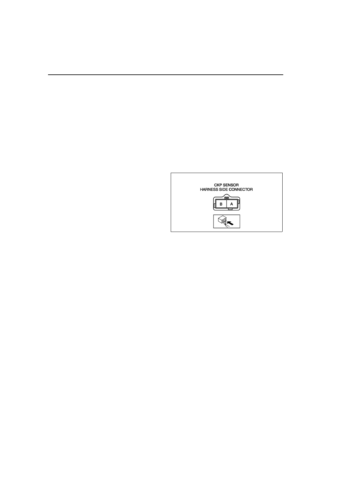
2. Measure the resistance between CKP sensor terminals A and B using an ohmmeter.
• If not as specified, replace the CKP sensor.
• If CKP sensor resistance is okay, but RPM PID value is out of specification, perform the “Circuit Open/Short
Inspection”.
Specification
400—550 ohms
Circuit Open/Short Inspection
1. Disconnect the PCM connector. (See
2. Inspect the following wiring harnesses for open or
short. (Continuity check)
Open circuit
• If there is no continuity, the circuit is open. Repair
or replace the harness.
— CKP sensor terminal A (harness-side) and
PCM terminal 2D (harness-side)
— CKP sensor terminal B (harness-side) and
PCM terminal 2G (harness-side)
Short circuit
• If there is continuity, the circuit is shorted. Repair
or replace the harness.
— CKP sensor terminal A (harness-side) and power supply
— CKP sensor terminal A (harness-side) and body GND
— CKP sensor terminal B (harness-side) and power supply
— CKP sensor terminal B (harness-side) and body GND
End Of Sie
CRANKSHAFT POSITION (CKP) SENSOR REMOVAL/INSTALLATION
A6E394018230W02
Removal
1. Perform the following procedure to making the working space.
(1) Remove the Front wheel (RH).
(2) Remove the splash shield.
2. Disconnect the CKP sensor connector.
3. Remove the installation bolts to remove the CKP sensor.
Installation
Caution
• When foreign material such as an iron chip is on the CKP sensor, it can cause abnormal output
from the sensor because of flux turbulence and adversely affect the engine control. Be sure there
is no foreign material on the CKP sensor when replacing.
1. Perform the following procedure so that piston No.1 is at the top dead center.
(1) Remove the front driveshaft (RH). (See
M–17 DRIVE SHAFT REMOVAL/INSTALLATION
A6E3940W012