Mazda 6. Manual - part 84
 

  Index      Mazda     Mazda 6 - service repair manual 2002 year


Search            


Content   ..  82  83  84  85   ..


Mazda 6. Manual - part 84


BASIC SYSTEM 

U–9

U

Evaporator

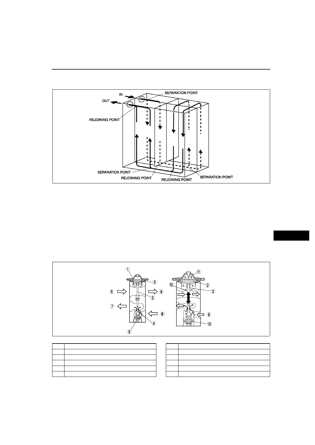
The double-tank drawn cup is the same as the previous model except that a new refrigerant flow pattern has 
been adopted. Due to this, size and weight reduction is achieved while maintaining performance.

Expansion Valve

The expansion valve causes a sudden decrease in the pressure of the liquid refrigerant. This atomizes the 
refrigerant, making it easier for the evaporator to vaporize it. The expansion valve also regulates the flow 
volume of the refrigerant sent to the evaporator.

The amount of refrigerant delivered to the evaporator is adjusted by the opening angle of the ball valve in the 
expansion valve.

Opening angle is adjusted by a balance of the R-134a pressure (Pb) in the diaphragm, and a composite force 
of evaporator discharge pressure (PI) against the lower part of the diaphragm and spring force (Fs) pushing up 
the ball valve. When PI increases, the temperature of the temperature sensor near the diaphragm rises and the 
Pd heated by the R-134a in the diaphragm increases. When the Pd increases more than PI + Fs, the 
diaphragm is pushed down, and the shaft attached to end of the temperature sensor rod pushes down the ball 
valve, increasing the amount of liquid refrigerant flow. When the evaporator discharge refrigerant temperature 
decreases, PI + Fs increases more than Pd, the ball valve is pushed up, and the amount of liquid refrigerant 
flow decreases.

.

A6E8516T007

A6E8516T003

1

Diaphragm

2

Temperature sensor

3

Shaft

4

Ball  valve

5

Spring

6

From evaporator

7

To evaporator

8

From condenser

9

To condenser

10

Spring force

11

HFC-134a pressure

12

Discharge pressure

U–10

BASIC SYSTEM 

End Of Sie

CONDENSER

A6E851661480T01

Construction

A sub cool condenser has been adopted. It is a multi-flow condenser which is equipped with a sub cooling part 
and integrated with a receiver/drier.

The sub cool condenser separates liquid-gas refrigerant initially cooled at the condenser via the receiver/drier, 
where it returns again to the condenser sub cooling part and is cooled, accelerating liquefaction and improving 
cooling capacity.

.

End Of Sie

REFRIGERANT LINES

A6E851661460T01

Spring-lock coupling is used for pipe-to-pipe connections. As a result, pipes can be connected easily, 
maintenance of torque is unnecessary, and serviceability is improved.

There is a garter spring in the cage on the female side (cooler hose (LO) (L.H.D.), cooler pipe No.3, 4 (R.H.D.)) 
of spring-lock coupling type and the end of the pipe on the male side (A/C unit) is flared. When the pipes are 
being connected, the flared end of the male side forces the garter spring on the female side to expand, and by 
fully inserting the male side into the female side, the flared end is locked by the garter spring.

When the cooler hose (LO) (L.H.D.) or cooler pipe No.3, 4 (R.H.D.) is replaced, the additional indicator ring 
comes out after connection, indicating that the flared end is locked.

.

A6E8516T004

1

Condenser

2

Cooling part

3

Sub cooling part

4

Receiver/drier

A6E8516T001

1

Female side

2

Cage

3

Garter  spring

4

Male side

5

Flared  end

6

Indicator ring

7

Unlocked

8

Locked

CONTROL SYSTEM 

U–11

U

End Of Sie

CONTROL SYSTEM

A6E854001042T10

L.H.D.

CONTROL SYSTEM

A6E8500T003

A6E8500T004

U–12

CONTROL SYSTEM 

R.H.D.

.

End Of Sie

A6E8500T005

A6E8500T006

1

Manual air conditioner

2

Full-auto air conditioner

3

Air intake actuator

4

Air mix actuator

5

Airflow mode actuator

6

Blower  motor

7

Resister

8

Power MOS FET

9

Magnetic clutch

10

A/C relay

11

Blower relay

12

Solar radiation sensor

13

Ambient temperature sensor

14

Cabin temperature sensor

15

Evaporator temperature sensor

16

Water temperature sensor

17

Refrigerant pressure switch

18

Thermal protector

19

Climate control unit

20

PCM

21

TNS relay

22

Rear window defroster relay


Content   ..  82  83  84  85   ..