Mazda 6. Manual - part 16
COOLING SYSTEM
E–7
E
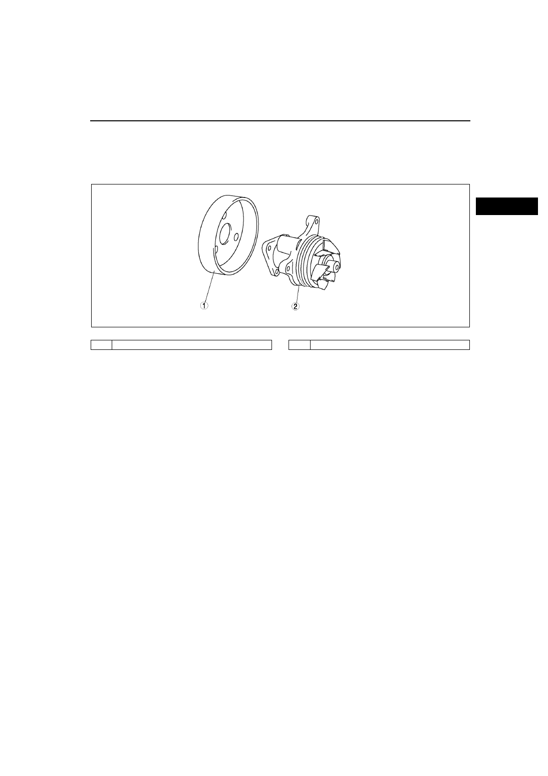
WATER PUMP
A6E363015010T01
Structure
•
The water pump body is made of aluminum alloy for weight reduction.
•
The impeller is built into the cylinder block and the water pump is not seviceable and must be replaced as a unit
if faulty.
•
The water pump is driven by the front drive belt. (sirpentain type)
•
.
End Of Sie
AME3602N006
1
Water pump pulley
2
Water pump body